The Goodness of Compasses consists chiefly in this, That the Motion of their Head be very equable, that so they may not leap in opening and shutting; that the Joints be well fitted; that they are well filed and polished; and, lastly, that the Steel-Points are well joined and equal. The Figure A sheweth these kinds of Compasses, whose Construction we shall give in the third Book.
Book I.
Ch. I.
Of the Construction and Use of the Compasses, the Ruler, the Drawing-Pen, and the Porte-Craion or Pencil-holder.
There are several Sorts of Compasses, of which we shall speak more fully hereafter; but that whose Uses we intend to lay down in this Chapter, is the common Pair of Compasses.
Of these Compasses there are two kinds, viz. Simple Ones, which have their Points fixed, and others whose Points may be taken off; both kinds being of different Bignesses, but they are commonly in Length from three to six Inches. To these Compasses, that shift their Points, there belongs a Drawing-Pen-Point, a Pencil-Point, and sometimes a Dotting-Wheel, to make dotted lines.
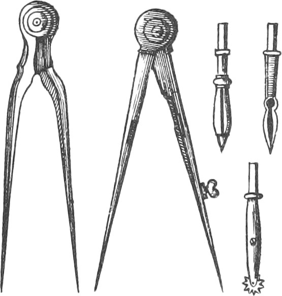
Rulers, which are of Brass, or Wood, ought to be very strait every way; they are made strait with Files and a Planner, whose Bottom is Steel; as also by rubbing them and another very strait Ruler together: one Side of these Rulers is sloped, to keep the Ink from blotting the Paper.
When Lines are drawn with Ink, they ought to be very fine.
To know whether a Ruler be very strait or not, draw a right Line upon a Plane; then turn the Ruler about, and apply the same Edge to the Line; and if the Edge of the Ruler exactly agrees with the right Line, it is a Sign the Ruler is very strait.

The Drawing-Pen is made of two Steel Blades joined together, and fastened to a little Pillar, at the other End of which is a Porte-Craion; there is a Cavity between the aforesaid Blades, in which Ink is put with a Pen: also the Blades must join each other in Points that be very equal. There is likewise a small Screw, serving more or less to open the Blades, that so Lines may be drawn fine or coarse, according to necessity.
The Porte-Craion ought to be of equal Bigness every where, and very straitly slit down the middle with a fine Saw; also the Porte-Craion is bent towards the end, in order to fasten a Pencil in it, by means of a little Ring.
Use I. To divide a right Line into two equal Parts.
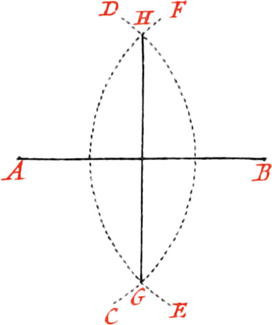
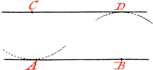
Let the given Line be AB, which is to be divided into two equal Parts: About the Point A, as a Center, or one of the Ends of the Line, describe the circular Arc CD, with your Compasses opened to any Distance, but nevertheless greater than one half of AB. Likewise about the other end B, as a Center, describe, with the same Opening of your Compass, the circular Arc EF, cutting the former Arc in the Points GH; then place a Ruler upon these two Intersections, and draw the Line GH, which will divide the Line AB into two equal Parts.
Note, The two Arcs will not intersect each other, if the Opening of the Compasses be not greater than half of the given Line.
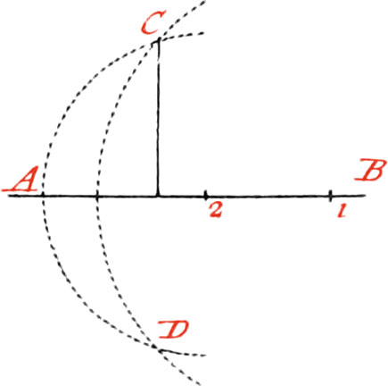
Use II. Upon a right Line, and from a Point give in it, to raise a Perpendicular.
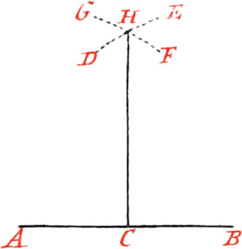
Let the given right Line be AB, and the Point given in it C, upon which it is required to raise a Perpendicular.
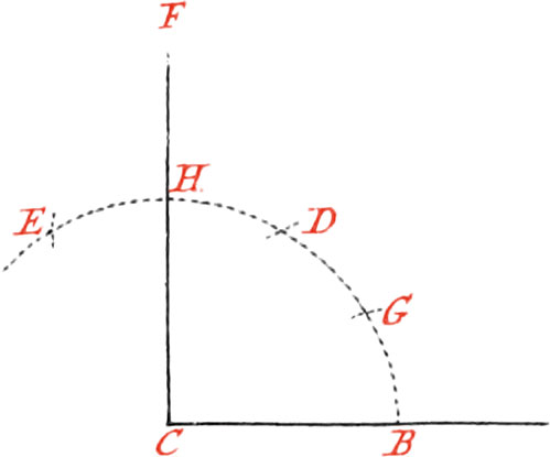
From the given Point C, mark both ways with your Compasses, on the given Line, the equal Distances CA, CB; then about the Points AB, as Centers, and with any opening of your Compasses (greater than half the given Line) describe the Arcs DE, FG, interacting each other in the Point H, and draw the Line HC, which will be perpendicular to AB.
If the given Point C be at the End of the Line, describe about the Point C, as a Centre, any Arc of a Circle; on which take twice the same opening of your Compasses, viz. from B to D, and from D to E: then about the Points D, E, describe two Arcs, intersecting one another in the Point F; lay a Ruler upon the Points F and C, and draw the Line FC, which will be a Perpendicular upon the End of the Line CB.
If there is not room to take the Length of DE, divide the Arc BD in two equal Parts in the Point G, and make DH equal to DG; then the Line HC will be a Perpendicular.
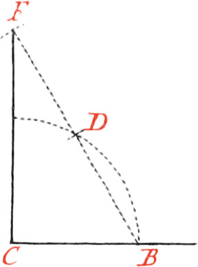
Or otherwise, having drawn the indefinite Line BDF, through the Points D, F, and made DF equal to BD; FC will be a Perpendicular.
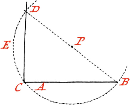
Or again in this Manner: having taken the Point P at pleasure above the given Line, about the said Point, as a Center; and with the Interval PC, describe the Arc BCD, then draw the Line BP, and produce it ’till it cuts the aforesaid Arc in the Point D, and from the Point D to the Point C, draw the Perpendicular DC.
Use III. From a Point given without a Line, to let fall a Perpendicular to the said Line.
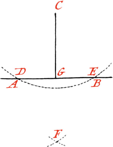
Let the given Point be C, from which, to the given Line AB, it is required to draw a Perpendicular. About the Point C, as a Center, describe an Arc of a Circle cutting the Line AB in the two Points DE; then from the Points DE, make the Intersection F; lay a Ruler upon the Points C and F, and draw the Perpendicular CG.
Note, The Intersection F may be made above or below the given Line; but it is bed to have it below it; because when the Points CF are at a good Distance, the Perpendicular may be drawn truer than when they are nigh.
When the Portion of the Circle described about the Point C, does not cut the Line AB in two Points, the Line must be continued if it can; if it cannot, Recourse must be had to the Method of Fig. 5. for raising a Perpendicular on the End of a Line: as suppose a Perpendicular is to be let fall from the Point D, on the Line CD, draw, at pleasure, the Line DB, which bisect in the Point P; then about this Point, as a Centre, and with the Distance PD, describe the Arc DCB, cutting the Line AB in the Point C. Lastly, lay a Ruler upon the Points C and D, and draw the Line CD, which will be the Perpendicular required.
Otherwise, let AB be the given Line, and C the Point without it; take two Points 1 and 2 at pleasure, on the said Line AB; then about the Points 1 and 2, and with the Distances 1C, 2C, describe Arcs of Circles, intersecting each other in two Points, as in C and D; then lay a Ruler on the two Intersections, and draw a Line, which will be the Perpendicular required.
Use IV. To cut a right-lined Angle into two equal Parts.
Let ACB be the Angle to be cut into two equal Parts.
About the Point C, as a Center, describe the Arc DE at pleasure; then about the Points D and E, describe two other Arcs, cutting each other in the Point F, and draw the Line FC through the Points F, C, which will cut the given Angle into two equal Parts.
If it be required to divide the Angle ACB into three equal Parts, the Arc DE must tentatively be divided by your Compasses into three equal Parts1; because the Trisection of an Angle by right Lines, hath not yet been geometrically found.
Use V. To raise a right Line on a given Line, that may incline no more than one Side than the other.
Make the same Operation as before, and produce the Line FCG.
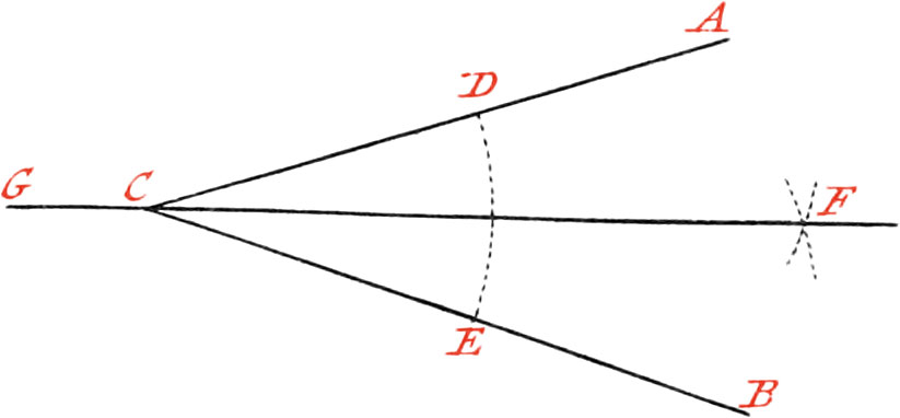
Use VI. Upon a given right Line, and from a Point given in it, to make an Angle equal to a given Angle.
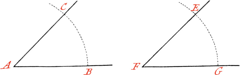
Let AB be the given Line, and A the given Point upon which it is required to make an Angle equal to the given Angle EFG.
About the Point F, as a Center, describe the Portion of a Circle; and with the same, opening of your Compasses, describe about the Point A another Portion; then take the Bigness of the Arc EG between your Compasses, which Distance lay off on the Arc BC: now through the Points A, C, draw the Line AC, and the Angle BAC will be equal to the Angle EFG.
Use VII. To draw a Line from a given Point, parallel to a given Line.
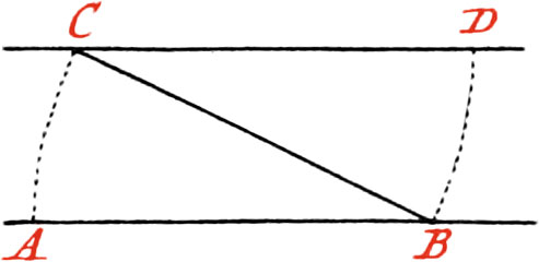
Let AB be the given Line, and C the Point through which it is required to draw a Line parallel to AB.
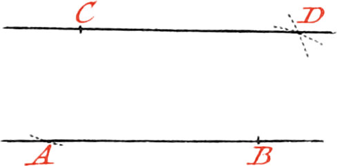
About the Point C, as a Center, and with any opening of your Compasses, taken at pleasure, describe the Arc DB cutting the given Line in the Point B: also about the same Point B, as a Center, and with the same opening of your Compasses, describe the Arc CA; then take the Distance of the Points C, A, and lay it off from B to D, and through the Points C and D, draw the Line CD, which will be parallel to AB.
Otherwise, about the Point C, as a Center, describe an Arc touching the given Line; and about another Point, taken at pleasure in the Line AB, describe, with the same opening of your Compasses, the Arc D: then through the Point C, draw a Line touching the Arc D, and the Line CD will be parallel to AB.
But as it is difficult to find whereabouts the Point of Contact will be, there is another way which is better, and is thus:
About the Point C, as a Center, and with any Distance, describe an Arc cutting the Line AB in A.
And about another Point in the same Line, as B, describe another Arc, with the same opening of your Compasses; then open the Compasses to the Distance AB, and about the Point C, as a Center, describe an Arc cutting the former one in the Point D; and through the Points C and D draw a Line, which will be parallel to AB.
Use VIII. To divide a given Line into any number of equal Parts.
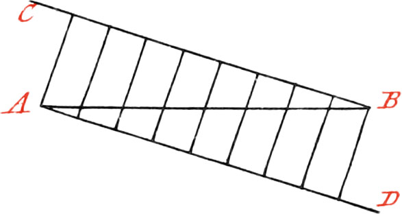
Let the Line given be AB, which is required to be divided into eight equal Parts: first, draw the Line BC, at pleasure, making any Angle with the Line AB. Likewise draw the Line AD parallel to BC; then divide BC into eight equal Parts, taken at pleasure, and make the same Parts on the Line AD, and through the Divisions of them, draw Lines, which will divide the Line AB into eight equal Parts.
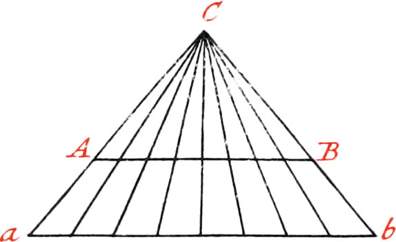
Or otherwise, draw the Line ab parallel to AB, which is proposed to be divided; then take 8 equal Parts on the Line ab. Now through the Ends of the two Parallels draw two Lines, which form Triangles with the Parallels, and intersect each other in the Point C; then from the Point C, draw Lines to the Divisions made on the Line ab, which will cut the Line AB in the Number of equal Parts required.
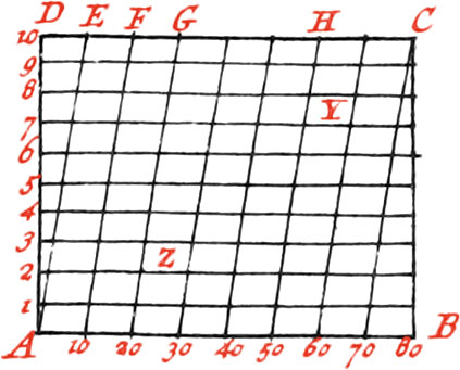
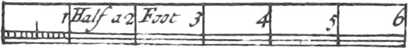
This Division of Lines serves to make Diagonal Scales; as suppose the Line AB is to make a Scale of eighty Parts, or eighty Fathom; each Part of this Line, divided into eight, contains ten Fathom: but since it is difficult to divide each of the aforesaid Parts into ten others, you must raise from the Ends of the Line AB, the Perpendiculars AD and BC, on which take ten Parts at pleasure; from every of which, you must draw Parallels to the Line AB; then the same Divisions must be made on the Line DC, as on AB; and the transversal Lines AE, 10F, 20G, &c. must be drawn.
Now it is easy to take off any Number of Fathoms from this Scale: as, for Example, to take off 23 Fathoms; Take the Concourse of the Transversal 20G, with the Parallel 3, that is at the Point Z, and Z3 will be 23 Fathom. Moreover, if 58 Fathom is required, take the Concourse of the Transversal 50H, with the Parallel 8, which is Y, and Y8 will represent 58 Fathom, and so of others. Feet might be put upon this Scale, by making a greater Distance between the Parallels; and by sub-dividing them into 12 equal Parts, there would be obtained Inches.
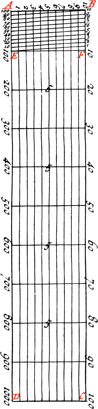
But now divide a very short Line into a great Number of equal Parts, as into 100 or 10000: For Example; Suppose the Line AD is to be divided into 1000 equal Parts; first, from the Ends AD, raise the Perpendiculars AB, DC, and divide each of these Perpendiculars into 10 equal Parts, and draw through the Divisions the like Number of Parallels to AD; then divide each of the Lines AD, BC into 10 equal Parts, which join by the like Number of Perpendiculars. Again, subdivide the first Space AE, and it’s Parallel, into 10 more Parts, which join by transversal or oblique Lines, as the Line E1, &c.
By this Means the first Interval AE, will be divided into 100 equal Parts; for which Reason, the Numbers 200, 300, 400, 500, &c. to 1000, are placed on this Scale, as may be feen in Fig. 16.
The Manner of taking of any Number of equal Parts from the aforesaid Scale, is the same as that which hath been already hewn in the precedent Figure. We shall again mention this Scale in the Chapter of the Sector.
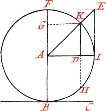
There are also Sines, Tangents, and Secants, projected upon Scales, in the following Manner: If from each Degree of the Quadrant IF, beginning from the Point I, Perpendiculars are let fall to the Radius AI, there will be the Sines of each Degree, the greatest of which is the Radius of the Circle, or Sinus Totus AF, and the Lengths of all these Sines may be projected upon the Radius, in order to make a Scale, beginning from the Point A; as the Sine DK is laid off from A towards G, &c.
And if the Tangent IE, be indefinitely produced toward E, and from the Center A, Lines, as AE, be drawn through each Degree of the Quadrant, to the Tangent IE produced, these will be the Secants of each Degree of the Quadrant. Whence it is manifest, that any one of the Secants is greater than the Radius AI. It is likewise plain, that every Tangent IE, is terminated by it’s Secant AE, in the Line IE, which will be a Scale of Tangents: and it is in this manner, that the simple Scales of Sines, Tangents, and Secants, are made in taking between your Compasses each of those Distances, and laying them off upon a Ruler. The Tables of Sines, Tangents, and Secants, are likewise made on this Principle: for the Radius of a Circle, or Sine of a right Angle, is supposed to be divided into 10000, and then there is found how many of these Parts every right Sine contains; as also the Tangents and Secants from one Minute to 90 Degrees; which, when put in order, are called the Tables of Sines, Tangents, and Secants.
Logarithms are Numbers in an Arithmetical Progression, to which answer other Numbers in a Geometrical Progression, as the two following Progressions.
Prog. Geom. Num. 1, 2, 4, 8, 16, 32, 64, 128, 256, &c.
Prog. Arith. Log. 0, 1, 2, 3, 4, 5, 6, 7, 8, &c;. Logarithms were invented to perform Multiplication by only the help of Addition, and Division by Subtraction; by which Operations are infinitely shortened, and so they are of excellent Use in Astronomical Calculations.
Note, The Use of these Tables is explained in Books of the Tables of Sines, Tangents, and Secants.
Use IX. To cut off from a given Line any Part assigned.
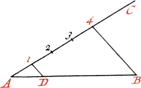
Let the Line AB be the given Line from which it is required to cut off the fourth Part.
Draw the indefinite Line AC, making any Angle with the Line AB, which divide into four equal Parts at pleasure; then from the last Division, draw the Line B4, and afterwards the Line D1, parallel to B4, which will be a fourth Part of AB.
Use X. To draw a right Line through a given Point, that shall touch a Circle.
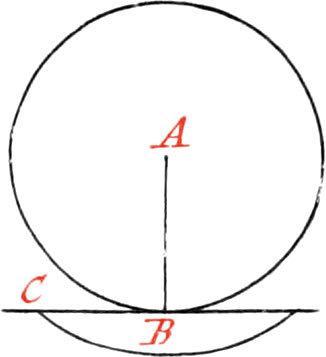
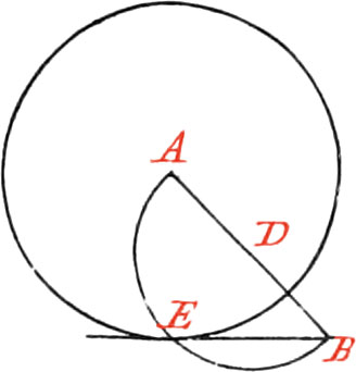
If the given Point be in the Circumference, draw the Radius AB, and on the Point B raise the Perpendicular BC, which will be the Tangent in the Point B. But if the given Point B be without the Circle, draw a right Line from the Center A, to the Point B, which bisect in the Point D: then about the said Point D, as a Center, and with the Distance BD, describe a Semi-Circle cutting the Circle in the Point E, and draw BE, which will be a Tangent.
If a Circle be given with it’s Tangent, and the Point of Contact be required, let fall the Perpendicular AB from the Center of the Circle, and the Intersection of the Tangent with the said Perpendicular, will be in the Point of Contact.
Use XI. Upon a given Line to describe a Spiral, making any Number of Revolutions.
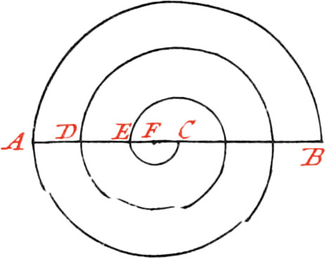
Let the given Line be AB, upon which it is required to describe a Spiral of 3 Revolutions. First, bisect that Line in the Point C, about which Point, as a Center, describe a Semi-Circle, whose Diameter may be equal to the given Line AB; then trisect the Semi-Diameter AC in the Points DE, and about the same Center describe, on the same Side the Line AB, two other Semi-Circles passing through the Points DE: again, subdivide the Space CE, into two equal Parts in the Point F; about which, as a Center, describe on the other Side of the given Line, three other Semi-Circles, and a spiral of three Revolutions will be had. If the Spiral is required to make four Revolutions, you must divide the Semi-Diameter AC into 4 equal Parts.2
Use XII.
Num. I.
Upon a given right Line, to describe an equilateral Triangle.
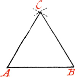
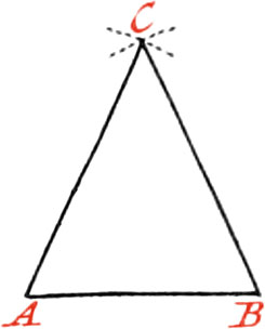
Let AB be the given Line on which it is required to describe an equilateral Triangle. About the Point A, and with the Distance AB, describe an Arc of a Circle; and about the Point B, as a Center, with the Distance BA, describe another Arc cutting the precedent one in the Point C; then draw the Lines CA, CB; and the Triangle ABC, will be an equilateral Triangle.
Use XII.
Num. II.
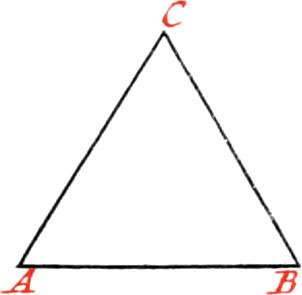
Upon a given right Line AB to describe an Isoscelles Triangle, one of whose equal Legs given.
About the Point A, as a Center, with your Compass opened to that given Distance, describe a small Arc of a Circle, and about the Point B with the same Opening, describe another small Arc cutting the former one in the Point C. Draw AC and BC, then will lie Triangle ABC be an Isoscelles Triangle, described upon the given Base AB, and having either of its equal Legs AC, BC of a given Length.
Use XIII. Upon a given right Line, to make a Triangle equal and similar to a given one.
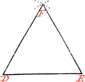
Let the given Triangle be ABC, to which it is required to make another similar, as DEF. Make the Line DE equal to AE; then about the Point D, as a Center, and with the Radius AC describe an Arc; also about the Point E, as a Center, and with the Radius BC describe another Arc, cutting the former one in the Point F; then draw the Lines DF, EF, and there will be a Triangle made equal and similar to the given one.
Use XIV. Upon a given right Line to make a Triangle similar to a given one.
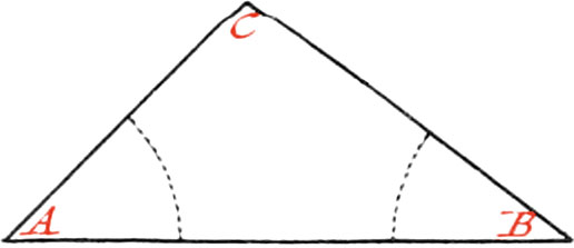
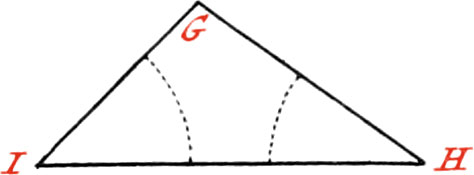
Let the given Line be HI, upon which it is required to make a Triangle similar (but not equal) to the Triangle ABC.
Make the Angle H equal to the Angle B, and the Angle I equal to the Angle A; then draw the Lines HG, IG, ’till they meet each other, and the Triangle HIG will be that required.
Use XV. To make a Triangle of three right Lines given; but any two of them must be longer than the third.
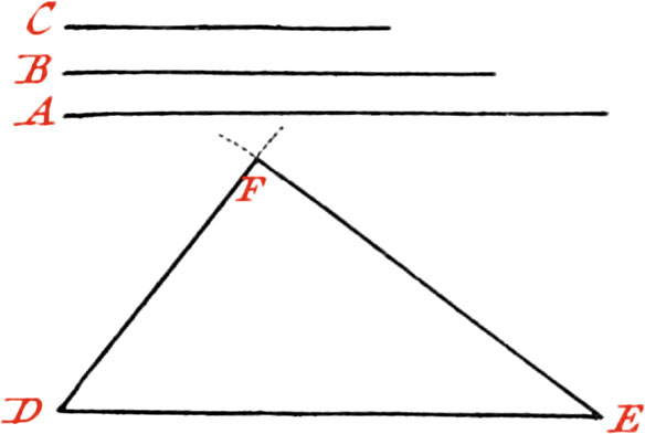
Let the three given Lines be A, B, C; first make the Line DE equal to the Line A, and about the Point E as a Center, with an Interval, equal to the Line B, describe the Portion of a Circle; also about D, as a Center, with an Interval equal to C, describe another Portion of a Circle, cutting the former one in the Point F; then draw the right Lines FD, FE, and the Triangle DFE will be that required.
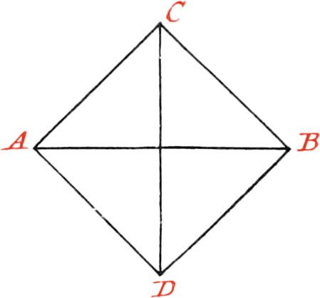
Use XVI. Upon a given right Line to make a Square
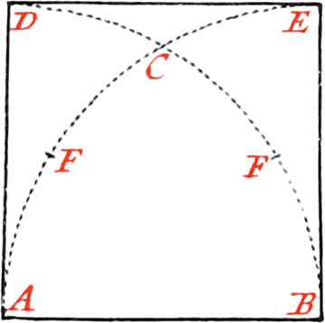
Let the given Line be AB, on which it is required to describe a Square, whose Side may be equal to the given Line, first about the Point A, as a Center; and with the Distance AB, describe the Arc BD, and about the Point B the Arc AE, intersecting it in the Point C, and divide the Arc CA, or CB, into two equal Parts in the Point F: now make the Intervals CE, and CD, equal to CF, and draw the Lines AD, BE, DE, and the Square will be made.
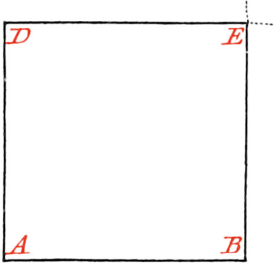
Or, otherwise, upon the End of the Line AB, raise the Perpendicular AD equal to AB, and about the Point D, as a Center, with the Distance AD, describe an Arc; likewise, Fig. 30. with the same Opening of your Compasses about the Point B, describe another Arc, and 31. cutting the first in the Point E, and draw the Lines AD, DE, EB, and the Square will be made.
I shall shew, in the Uses of the Protractor and Sector, how to make any regular Polygon upon a given Line; but, by the way, I shall give one general Method for constructing them, by means only of a Ruler and Compasses.
Use XVII. To inscribe any regular Polygon in a Circle.
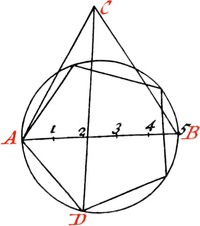
Suppose, for Example, a Pentagon is to be made: Now if the Circle be given, divide it’s Diameter into five equal Parts (by Use VIII.), but if it be not given, draw with your Pencil an indefinite Line for a Diameter, which being divided into five equal Parts, open your Fig. 32. Compasses the whole Extent of the Diameter, and setting one Foot of them upon the Ends of the Diameter, describe two Arcs intersecting each other in the Point C, that thereby an equilateral Triangle may be formed; then having drawn a Circle about the Diameter, lay a Ruler upon the laid Point C, and upon the second Division of the Diameter, and draw a Line, cutting the concave Part of the Circumference in the Point D, then the Arc AD will be nighly a fifth Part of the Circumference: therefore the Extent AD will divide the Circle into five equal Parts, and drawing five Lines, the proposed Polygon will be made.
This is a general Method to make all regular Polygons: As, to make a Heptagon, there is no more to do but divide the Diameter AB into seven equal Parts (that is, into as many Parts as the Figure hath Sides), and always drawing a Line from the Point C, thro’ the second Division of the Diameter.
The Construction of a Hexagon is simpler; because, without any Preparation, the Radius, or Semidiameter of the Circle, will divide the Circumference into six equal Parts.
And the Dodecagon is made in only bisecting each Arc of the Hexagon; therefore to make a Decagon, every Arc of the Pentagon must be bisected.
This Problem is almost the same as that described in cap. 17. lib. 1. of the Chevalier de Ville’s Fortification, except, that for dividing the Circle, he draws a Line from the exterior Angle of the equilateral Triangle, thro’ the first Point of Division of the Diameter, and afterwards he doubles the Arc of the Circle; but his Method is far from being exact: for, in the Description of a Pentagon, the Angle at the Center is too great by forty-four Minutes; in the Heptagon, it is too great one Degree and five Minutes; and so the Error will be augmented in Polygons of a greater number of Sides. But by making the Line pass thro’ the second Point of Division of the Diameter, the Angle at the Center of the Pentagon will be but about six Minutes too little, and in the Heptagon it is too great by about six Minutes; which are much less Errors, and almost insensible in the Description of the Polygons.
Use XVIII. To draw a Circle thro’ three given Points, provided they be not in a right Line.
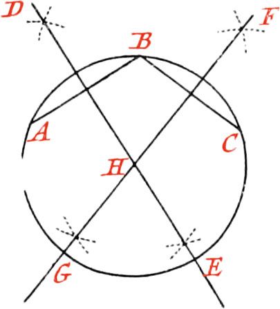
Let the given Points be A, B, C: first draw a Line from the Point A to the Point B, and another from the Point B to the Point C; both of which divide into two equal Parts by the Lines DE, FG, drawn at right Angles to them, and meeting each other in the Point H, Distance HA, HB, or HC, describe a Circle, and what was required will be done.
By this means the Circumference of a Circle begun, may be finished, in taking three Points in it, and proceeding as before.
Use XIX. To find the Center of a Circle.
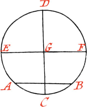
Let ABD be the given Circle, whose Center is required to be found; draw the Line AB, which bisect by the Line CD at right Angles: likewise bisect the Line BD by the Line EF, cutting the Line CD in the Point G, which will be the Center of the Circle.
Use XX. To draw a right Line equal to the Circumference of a Circle; and, contrariwise, to make the Circumference of a Circle equal to a given Line.
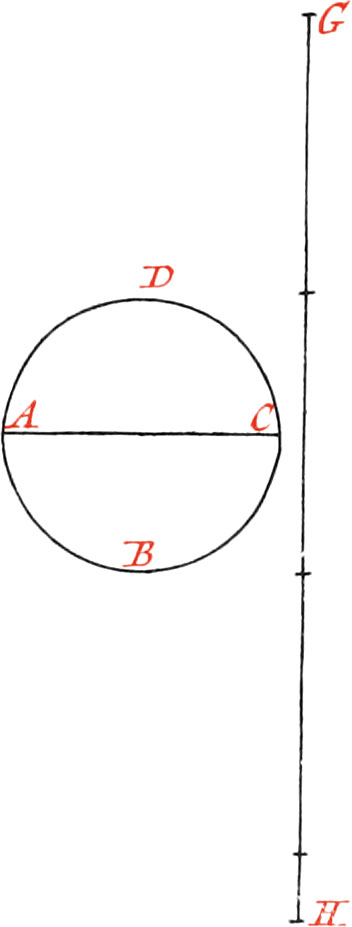
Let the given Circle ABCD be that whose Circumference it is required to make a right Line equal to: First draw a right Line, and lay off upon it three times and \(\frac{1}{7}\) of the Diameter, as from G to H; then this right Line GH will be almost equal to the Circumference of the Circle: I say almost; for if it could be exactly had equal to the Circumference, the Quadrature of the Circle would also be had,3 which hath not yet been Geometrically found.
Use XXI. To describe an Oval upon a given right Line.
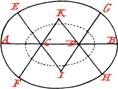
Let AB be the given Line, upon which it is required to describe an Oval; trisect it in the Points C and D; then upon the Part CD describe two equilateral Triangles, whose Sides produce; and about the Points C, D, with the Distance CA, or DB, describe Portions of a Circle to the Sides of the Triangles, produced to the Points E, F, G, H; then about the Points I, K, as Centers, and with the Radius IE, or IG, describe the Arc EG on one Side, and the Arc FG on the other, and the Oval will be made. Note, This is not properly an Oval, but something like one.
Use XXII. To describe an Ellipsis, having the two Axes given.
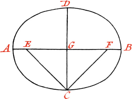
Let the great Axis be AB, and the small one CD, intersecting each other at right Angles in the Point G.
First take with your Compasses, or a String, half the Length of the great Axis, that is, AG, or GB; and with this Length setting one foot of your Compasses in the Point C, describe a Circle cutting the great Axis in the Points E, F, which will be the Foci of the Ellipsis. This being done, place Pins in these Foci; or, if the Ellipsis to be described be required large, and to be on the Ground, as in a Garden, drive Pegs into them: Then take a Thread, or String, equal in Length to the great Axis AB, and after having doubled it, put it about the two Pins or Pegs placed in the Foci E, F; so that the two Ends which you hold in your Hand may be in the End C of the small Axis: then holding a Pencil, or something else proper to make a Mark, in your Hand at C, move it round, keeping the String always tight ’till it, together with the Ends of the Thread or String, comes again to the Point C, and the Ellipsis ADBC will be described by the Pencil.
Note, This Method of describing an Ellipsis is the best of any; as also if the Thread, or String, be in Length augmented or diminished, without changing the Distance of the Foci, there will be hand Ellipses of another kind. Moreover, if without changing the Length of the Thread, or String, the Distance of the Foci be diminished, there will still be had another Species of Ellipses; and when the Foci’s Distance is infinitely diminished, a Circle will be described: But if the Length of the great Axis be augmented or diminished, together with the String (which is equal to it), in the same Proportion as the Distance of the Foci, all the Ellipses will be similar, but of different Magnitudes.
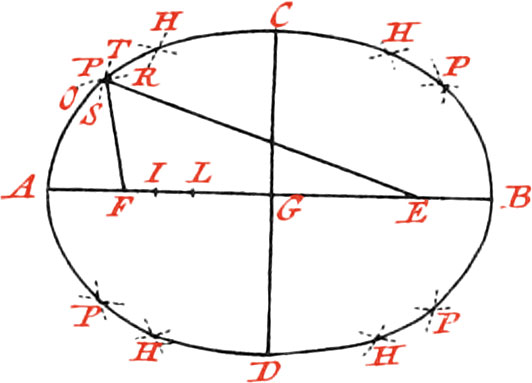
To draw an Ellipsis another way.
The two Foci E, F, being found (as in the precedent Figure), any Number of Points, thro’ which the Ellipsis must pass, may in this manner be found. Open your Compasses at pleasure to any Distance greater than AF, as to the Distance AI; then set one of their Points in the Focus F, and which the other describe the Arc OR; afterwards open the Compasses the Distance IB, which is the remaining part of the great Axis, and setting one of it’s Points in another Focus E, with the Distance IB describe the Arc ST, and the Point P of Intersection will be in the Periphery of the Ellipsis. In like manner, the Distances AL, LB, described about the Foci, will intersect each other in the Point H: and finally, by opening your Compasses to different Distances, any Number of Points may be found; which being joined, an Ellipsis will be had.
Note, Every Opening of your Compasses serves to find four Points equally distant from the Axes; as also if, from any Point taken at pleasure in the Periphery of an Ellipsis, to right Lines, as PF, PE, are drawn to the Foci; these will be both together and equal to the great Axis.
Use XXIII. To make one Figure equal and similar to another Figure.
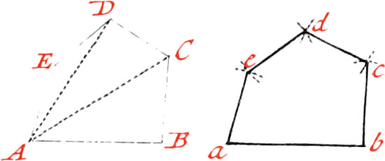
Let the proposed Figure ABCDE, to which another is to be made similar and equal.
First divide it into Triangles by the Lines AC, AD; and then draw the Line ab equal to AB; and about the Point b, with the Distance BC, describe an Arc: also about the Point a, and with the Distance AC, describe another Arc, cutting the former one in the Point c, and draw the Line bc: In like manner proceed for the other Side, and the Figure abcde will be similar to the proposed Figure ABCDE.
Use XXIV. To reduce great Figures to lesser ones, and contrariwise.
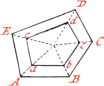
Because the Reduction of Figures is useful, there is here three ways given to reduce them.
First, a Figure may be reduced in taking a Point within it, and drawing Lines to all the Angles: For Example, let the Figure ABCDE be proposed to be reduced to a lesser.
Take the Point F, about the middle of the Figure, and draw Lines to all the Angles &c. and the Figure abcde will be similar to the figure ABCDE.
If a greater Figure be required, there is no more to do but produce the Lines drawn from the Center of the Figure, and then drawing Parallels to it’s Sides.
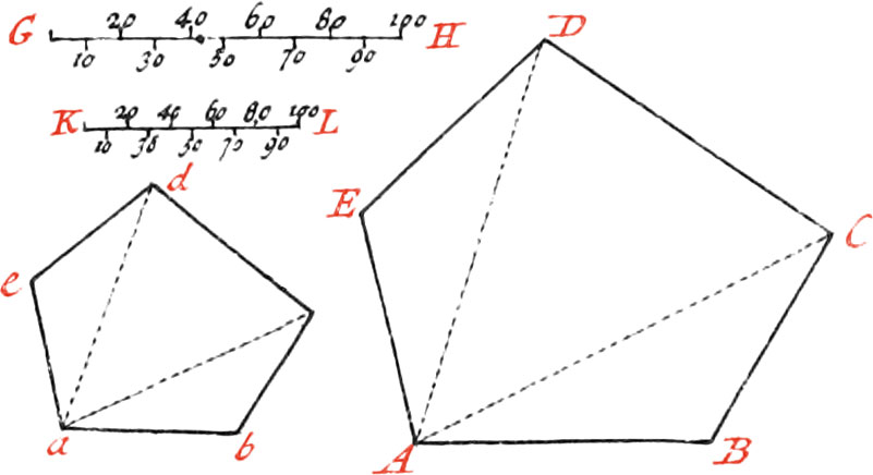
To reduce a Figure by the Scale.
Measure all the Sides of the proposed Figure ABCDE, with the Scale GH; then take another lesser Scale KL, containing as many equal Parts as the greater. Now make the Side ab as many Parts of the lesser Scale, as the Side AB contains of the greater one’s Parts; also make bc as many Parts as BC, and ac as many as AC, &c. by which means the Figure will be reduced to a lesser one.
To reduce a lesser Figure to a greater one, a greater Scale must be had, and proceed as before.

To reduce Figures by the Angle of Proportion.
Let the proposed Figure ABCDE be that which is to be diminished in the proportion of the Line AB, to the Line ab.
First draw the indefinite Line GH, and take the Length AB, and lay off from G to H; then about the Point G, describe the Arc HI. Again, take the Length of the given Side ab as a Chord of the Arc HI, draw the Line GI, and the Angle IGH will give all the Sides of the Figure to. be reduced.
As to have the Point c, take the Interval BC, and about the Point G describe the Arc KL; also about the Point b, with the Distance LK, describe a small Arc. Now take the Distance AC, and about the Point G describe the Arc MN; likewise about the Point a, with the Distance MN, describe an Arc, cutting the precedent one in the Point c, which will be that which must be had to draw the Side be: in like manner proceed for all the other Sides and Angels of the Figure.
If by this means a small Figure is to be reduced to a greater, the same manner of proceeding will do it; but the Side of the Figure to be augmented must be lesser than double of that answering to it. As for Example; to reduce the Figure abcde to a greater, the Side AB of the greater one, must be lesser than double the Side ab of the smaller one: for if it was double, the two Fines forming the Angle IGH, would directly meet each other, and make but one right Line.
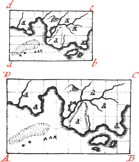
To reduce Figures by means of Squares.
This way particularly serves to copy, augment, or diminish a Map.
Let, for Example, the Map ABCD be proposed to be reduced to a lesser one. First, divide it into Squares, then make a lesser similar Figure abcd, which likewise divide into the same Number of Squares as you did ABCD. This being done, draw in every Square of the lesser Figure, what is contained in the correspondent Square of the greater Figure, and there will be a lesser Map. Note, The greater the Number of Squares are, the juster will the Figure be.
- 1Our Author should have said here, because the Trisection of an Angle cannot be geometrically performed by right Lines or Circles either. See more particularly how to do this in the Appendix.
- 2Although this is called a Spiral, yet in reality, it is only several unequal Semi-Circles; of no manner of use in any geometrical Effection, a Spiral being vastly different. See the Appendix.
- 3No, nor never will, it being impossible to be done.