Of the Construction and Uses of several Sorts of Compasses.
Having already treated Common Compasses, usually put into Cases of Instruments, we proceed now to mention some others, sometimes likewise placed in Cases of different Bignesses.
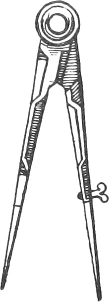
The Construction of Hair-Compasses.
Fig. A
These Compasses are so called, because of a Contrivance in the Body of them, by means of which an Extent may be taken into a hair’s Breadth. We have before hinted, that the Goodness of Compasses consists chiefly in having the Motion of their Head sufficiently easy, and that they open and shut very equally; and that they may do so, the Joints ought to be well slit, and very equal in Thickness.
The Manner of constructing the Joints, is thus: We first, with a Steel-Saw, slit the Head in two Places, so that there remains a Middle-Piece, the Thickness of a Card; then we slit the other Leg of the Compasses, in the Middle of the Joint, to receive the Middle-Piece which was reserved for that purpose; afterwards the Joints must be filed and straightned, so that they may be well joined every where. This being done, we drill a round Hole thorow the Middle of the Head, in Bigness proportional to that of the Compasses, for the Rivet to go through; the Rivet ought to be very round, and exactly fill the aforesaid Hole. When we have rivetted it, the Head of the Compasses must be warmed, and a little yellow Wax poured between the Joints, for lessening the Friction of the Legs in opening and shutting Lastly, we generally put upon the Head two turned Cheeks, serving for Counter-Rivets, and to preserve the Head.
The little Screw at the Bottom of the Body of these Hair-Compasses, is to move the Steel Point backwards or forwards, at pleasure: this Point is fastened to the Top of the Compasses by two Rivets, so that in turning the Screw it springs. The other Steel Point must be soldered to the other Leg, as all other Points of Compasses are that are fixed. Now to fit these Points for soldering, they must be filed so, as to go into two Slits made in the Bottom of the Body of the Compasses, that there they may be well joined, and the Solder strongly hold them.
Note, Solder is commonly made with Silver and Thirds of Copper, that is, twice. more Silver than Copper: For Example; with one Dram of Silver, we mix half a Dram of Copper, which must be first melted in a Crucible, and afterwards, when cold, hammered to about the Thickness of a Card, and cut into small Pieces that it may the sooner run, when there is use for it. Solder is likewise often made with Copper and Zink mixed together viz. In melting \(\frac{3}{4}\) of Copper, with \(\frac{1}{4}\) of Zink: in soldering, we use Borax finely bruised, which makes the Solder better run and penetrate the Joints, or any thing else to be soldered.
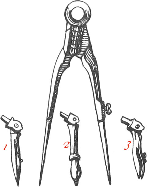
Of the German Compasses.
Fig. B
The Legs of these Compasses are something bent, so that, when shut, the Points only touch each other. One Point of these Compasses may be taken off, and others put on, by means of a small square Hole made in the Bottom of the Body, for the Points to go in, and a Screw to keep them fast when in: but these Points ought very well to fit the aforesaid square Hole, that they may not shake.
The Points generally put on, are,
First, A Drawing-Pen Point, by means of which, Lines fine or coarse may be drawn with Ink, by help of a little Screw near the Point of the Drawing-Pen. This Drawing-Pen Point, as well as the other Points to be put on, has a small Joint, almost like the Head of a Pair of Compasses, by means of which it may be kept perpendicular to the Paper, according as the Compasses are more or less opened. This Point is represented by Fig. 3.
Secondly, A Pencil-carrying Point, represented by Fig. 2, for drawing Lines with a Pencil.
And Lastly, a Dotting-Wheel Point, (Fig. 1.) whose Use is to make dotted Lines. What we call a Dotting-Wheel, is a little Wheel of Brass, or ether Metal, about 3 Lines in Diameter, round which is made little pointed Teeth. This Wheel is fastened between two little Pieces of Brass by a small Pin, so that it may freely turn round, almost like a Spur; but the said Teeth must not be too far distant from each other, because then the Dots the Wheel makes, will also be too far distant from each other.
The Construction of these Compasses as to their Joints, &c. being the same as those before spoken of, I shall only add, that since the Beauty of Compasses consists very much in their being well polished; for this effect, we first rub the Compasses with Slate-Stone dipped in Water; then we rub every part of the Compasses with a flat Stick of soft Wood, and a Mixture of Emery tempered with Oil, or fine Tripoly. And lastly, we wipe the Compasses clean with a Cloth or Piece of Shamoy.
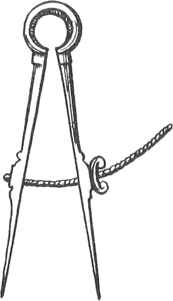
Of the Spring-Compasses.
Fig. C
These Compasses are all made of tempered Steel, which are so hard every where, that a File cannot touch them; and the Head of these Compasses is rounded, that by it’s Spring it opens and shuts itself: the Circular Screw fix’d to one of the Legs, serves to open or shut it, by means of a Nut. These Compasses are very fit to take small Lengths, and make small Divisions; yet they ought to be but short, and so tempered, that they may have a good Spring, and not break.
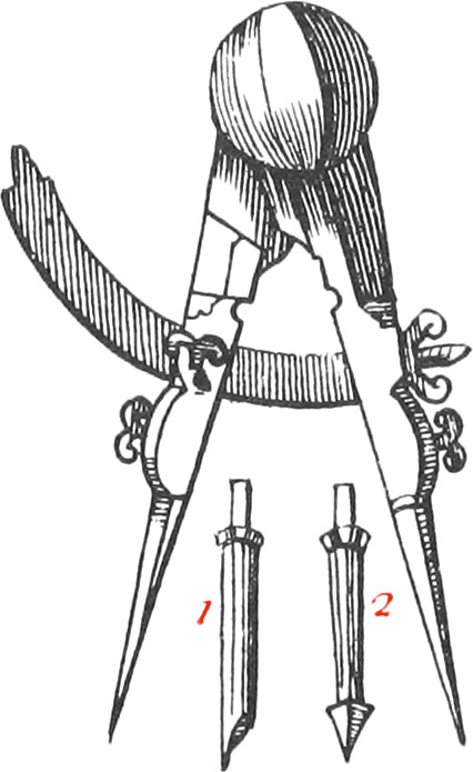
Of the Clock-makers Compasses.
Fig. D
These Compasses, which are strong and solid, serve to cut Part-board, Brass, and other the like things; the Quadrant crossing it, serves strongly to fix it to a proposed Opening, by help of a Screw pressing against it. The Nut at the End of the said Quadrant, is to open or shut the Compasses at pleasure, in turning the said Nut, which ought to be so riveted to the Leg of the Compasses, that it may make the other Leg move forwards or backwards. The Four Points ought to be made of well tempered Steel. That of Fig. 1. is filed slopewise, like a Graving-Tool, to cut Brass; that of Fig. 2. is like a pointed Button: and the two other Points are in figure of the fixed Points of common Compasses; but they must be very strong in proportion to the Compasses.
There are different ways of tempering the Points of Compasses, or other Pieces of Steel: For Example; the Points of small Compasses are tempered by means of a Lamp, and a small Brass Pipe: for blowing in the Pipe, causes a strong lively Flame, in which putting the Points, or other Things, to be hardened, and they will become almost instantly red hot, and when they are cold, they will be very hard. But the Points of great Compasses, and other Steel Tools, are tempered with a Charcoal Fire, by blowing thro’ the aforesaid Pipe, and heating them to a Cherry Colour, and afterwards putting them into Water, and then they will be rendered very hard.
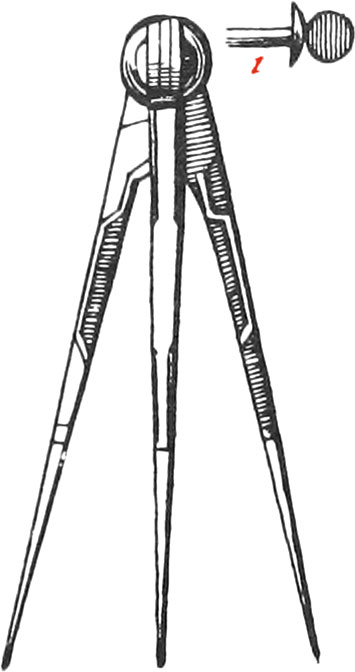
Of the Three-legged Compasses.
Fig. E
The Use of these Compasses is to take three Points at once, and so to form a Triangle, or to lay down three Positions of a Map to be copied at once, &c.
The Construction of these Compasses doth not much differ from the Construction of the others, excepting only that the third Leg has a Motion every way, by means of a turned Rivet, riveted by one End to the two other Legs; and at the other End there must be a turned Cheek, and a round Plate serving for a Joint to the third Leg: the little Figure 1 shows how the Rivet is made.
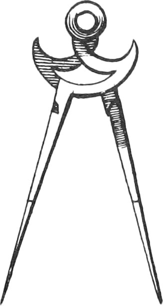
Of the Sea-Chart Compasses.
Fig. F
The Legs of these Compasses are crooked, and widened towards the Head, so that by pressing the two Legs with your Hand, you may open them. Their Construction sufficiently appears from the Figure, and their Use will be mentioned in the Instruments for Navigation.
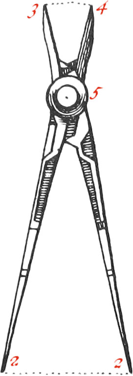
Of the simple Proportional Compasses.
Fig. G
These Compasses are used in dividing of Lines into 2, 3, 4, or 5 equal Parts, as also to reduce small Figures to greater ones, and contrariwise, &c. You must: take care in making these Compasses, that the Head be drilled in a right Line with the Legs, and that the Points are not one forwarder than another. Now if you have a mind to make one of these Pair of Compasses to take the \(\frac{1}{2}\) of a Line, the Distance from the Center of the Joint to the Ends of either of the longest Legs, must be twice the Length of either of the shortest Legs; and so in proportion for others. Note, The Compasses of Figure G, are for dividing of Lines into 3 equal Parts; whence the Distance from the Center marked 5, to the Points 2; 2, is three times the Distance from the said Center to the Points 3 or 4: So that if the third Part of the Line 2, 2, be required, it’s whole Length must first be taken between the longest Legs of the Compasses, which remaining thus opened, the Distance between the Points of the shortest Legs, will be \(\frac{1}{3}\) of the given Line.
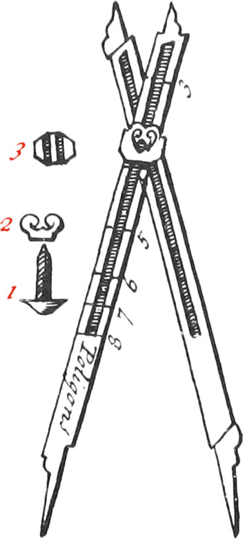
Of the Moveable-headed Proportional Compasses.
Fig. H
The Use of these proportional Compasses, is to divide a given Line into any Number of equal Parts, as also to divide the Circumference of a Circle, so that a regular Polygon may be inscribed therein.
These Compasses consist of two equal Legs, each of which is furnished with two Steel Points and are hollowed in, for a Cursor to slip up and down; in the middle of which Cursor, there is a Screw serving to join the Legs, and to fasten them in divers Places by means of a Nut: but the Legs must be hollowed in exactly in the Middle of their Breadth, that so the Center of the Cursor may be in a right Line with the Points of the Legs, and the Cursor slide very exactly along the Legs: as also the Head-Screw must exactly fill the Hole in the Cursor, so that nothing may shake when the Legs are fastened with the Nut.
Figure 1, represents the Screw, Figure 2, the Nut; Figure 3, half the Cursor, which must be joined by a like half. You may see by that little Figure, that there is a Piece in the Middle kit exactly to fit the Hollow of the Leg of the Compasses: the shadowed Spaces of the said Figure, are to contain the two Sides of the Leg; understand the same of the other half of the Cursor.
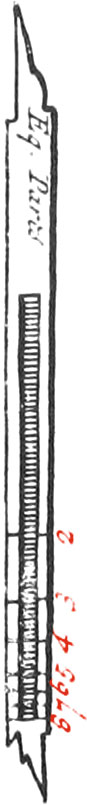
Fig. I
Figure I, is one of the Legs separate, upon which are the Divisions for equal Parts: for upon one Side of one of the Legs, are the Divisions for dividing of Lines into equal Parts; and upon one Side of the other Leg, are denoted the Numbers shewing how to inscribe any regular Polygon in a proposed Circle.
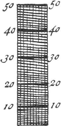
Now to make the Divisions for dividing Lines into equal Parts, take a well divided Scale, or a Sector, which is better, because it is almost a universal Scale: then take the exact Length of one of the Legs of your proportional Compasses between your Compasses, and having opened the Sector, so that the Distance between 120 and 120 of the Line of Lines be equal to that Extent, take the Distance from 40 to 40, which lay off upon the Leg of your Compasses, and at the End thereof, set the Number 2, which will serve to divide any given Line into two equal Parts: The Sector still continuing opened to the same Angle, take the Distance from 30 to 30, on the Line of equal Parts, and lay off upon the aforesaid Leg of the Compasses, where set down the Number 3, and that will give the Division for taking 4 of any given Line. Again; take 24 equal Parts, as before, from the Line of Lines, lay them off upon the Leg, and that will give the Division for dividing a Line into 4 equal Parts.
Moreover, take 20 equal Parts, and that will give you the Division upon the Leg of the Compasses, serving to divide a Line into 5 equal Parts: the same Opening of the Sector will still serve to divide a Line into 7, 9, and 11 equal Parts. But to avoid Fractions, the aforesaid Opening must be changed, to make the Division of 6, 8, 10, and 12, upon the Leg: but before the said Opening of the Sector be altered, take the Distance from 15 to 15, which will give the Divisions for dividing a Line into 7 equal Parts.
Again; Take 12, and that will give the Division for dividing a Line into 9 equal Parts; and lastly, the Distance from 10 to 10, will give the Division for dividing any Line into 11 equal Parts.
But to make the Division for dividing a Line into 6 equal Parts, take between your Compasses the Length of one of the Legs of the proportional Compasses, and open the Sector so, that the Distance between 140 and 140, on each Line of equal Parts, be equal to the aforesaid Length. The Sector remaining thus opened, take the Distance from 20 to 20, on each Line of equal Parts, and lay it off upon the Leg of the Compasses, and that will give the Division for dividing a Line into 6 equal Parts.
Again; having taken the Length of the Leg of your Compasses, open the Sector, so that the Distance from 180 to 180, of each Line of equal Parts be equal thereto. Then take the Extent from 20 to 20, and that laid off upon the Leg of the Compasses, will give the Division for dividing a Line into 8 equal Parts.
Moreover, open the Sector so, that the Distance from 110 to no, be equal to the Length of the Leg of your Compasses. The Sector remaining thus opened, the Distance from 10 to 10, will give the Division for dividing a Line into ten equal Parts.
Lastly, the Sector being opened, so that the Length of the Leg of your Compasses be equal to the Distance from 130 to 130; and then the Distance from 10 to 10 will give the Division for dividing a Line into twelve equal Parts.
The Use of this Line is easy: for suppose a right Line is to be divided into three equal Parts; first push the Cursor, so that the Middle of the Screw may be just upon the Figure 3; and having firmly fixed it upon that Point, take the Length of the proposed Line between the two longest Parts of the Legs; then the Distance between the two shortest Parts of the Legs will be \(\frac{1}{3}\) of the given Line. Proceed thus for dividing a given Line into other equal Parts.
Now to make the Divisions for regular Polygons, divide the Leg of your Compasses into two equal Parts; and having opened the Sector, let the Distance from 6 to 6, on the two Lines of Polygons, be equal to one of those Parts. The Sector remaining thus opened, take the Distance from 3 to 3 for a Trigion, and lay it off from the End of the Leg of your proportional Compasses, where mark 3. Again, take the Distance from 4 to 4 for a Square, upon the Line of Polygons, and that will give the Division for a Square. Moreover, take the Distance from 5 to 5, on the Lines of Polygons, and lay off upon the Leg of your Compasses, which will give the Division for a Pentagon; proceed thus for the Heptagon, and the other Polygons, to the Dodecagon. It is needless to make the Division for a Hexagon, because the Semidiameter of any Circle will divide it’s Circumference into six equal Parts.
The Use of this Line for the Inscription of Polygons is very easy: for if, for Example, a Pentagon is to be inscribed in a given Circle, push the Cursor so, that the Middle of the Screw may be against the Number 5 for a Pentagon; then with the shortest Parts of the Legs, take the Semidiameter of the Circle; and the Legs remaining thus opened, the Distance between the Points of the longed Parts of the Legs, will be the Side of a Pentagon inscribed in the given Circle.
Again, suppose a Heptagon is to be inscribed in a Circle; fix the Screw against the Number 7; then take the Semidiameter of the Circle between the longest Parts of the Legs of your Compasses, and the Distance between the shortest Parts of the Legs will be the Side of a Heptagon inscribed in the said Circle.
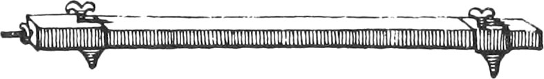
Of the Beam-Compass.
Fig. K
This Compass consists of a very even square Branch of Brass or Steel, from 1 to 3 or 4 Feet in Length. There are two square Brass Boxes or Cursors exactly fitted to the said Branch, upon each of which may be screwed on Steel, Pencil, or Drawing-Pen Points, according as you have use for them. One of the Cursors is made to slide along the Branch, and may be made fast to it by means of a Screw at the Top thereof, which presses against: a little Spring; the other Cursor is fixed very near one End of the Branch, where there 15 a Nut so fastened to it, that by turning it about the Screw, at the End of the Branch, the said Cursor may be moved backwards or forwards at pleasure.
These Compasses serve to take great Lengths, as also exactly to draw the Circumferences of great Circles, and exactly divide them.
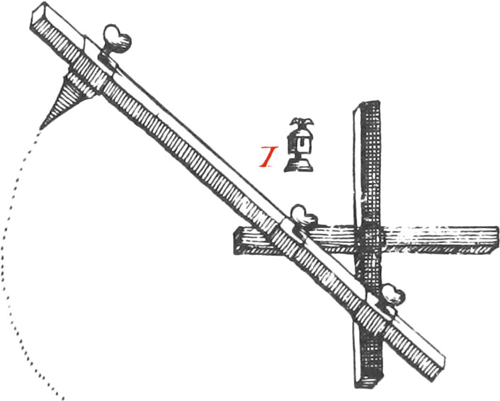
Of the Elliptick-Compasses.
Fig. L
This Instrument, whose Use is to draw Ellipses of any kinds, is made of a cross Branch of Brass, very strait and equal, about a Foot long, on which are fitted three Boxes, or Cursors, to slide upon it. To one of the Cursors there may be screwed on a Steel-Point, or else one to draw with Ink, and sometimes a Porte-Craion. At the Bottom of the two other Boxes are joined two sliding Dove-Tails (as the little Figure 1 shews), these sliding Dove-Tails are adjusted in two Dove-Tail Grooves, made in the Branches of the Cross. The aforesaid two sliding Dove-Tails, which are affixed to the Bottoms of the Boxes by two round Rivets, and so have a Motion every way, by turning about the long Branch, move backwards and forwards along the Cross; that is, when the long Branch has gone half way about, one of the sliding Dove-Tails will have moved the whole Length of one of the Branches of the Cross; and then, when the long Branch is got quite round, the same Dove-Tail will go back the whole Length of the Branch: understand the same of the other sliding Dove-Tail.
Note, The Distance between the two sliding Dove-Tails, is the Distance between the two Foci of the Ellipsis; for by changing that Distance, the Ellipsis will more or less swell.
Underneath the Ends of the Branches of the Cross, there is placed four Steel-Points, to keep it fast upon the Paper. The Use of this Compass is easy; for by turning round the long Branch, the Ink, or Pencil-Point, will draw an Oval, or Ellipsis, required. It’s Figure is enough to shew the Construction and Use thereof.
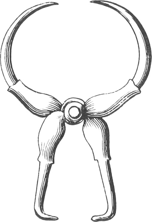
Of Cylindrick and Spherick Compasses.
Fig. M
Figure M is a Pair of Compasses used in taking the Thicknesses of certain Bodies, as Cannon, Pipes, and the like things, which cannot be well done with Compasses of but two Points. These Compasses are made of two Pieces of Brass, or other Metal, having two circular Points, and two flat ones, a little bent at the Ends. When you use them, one of the flat Points must be put into the Cannon, and the other without; then the two opposite Points will shew the Thickness of the Cannon.
Note, The Head of these Compasses ought to be well drilled in the Center; that is, if a Line be drawn from one Point to the opposite one, the said Line must exactly pass thro’ the Center; and when the Compasses are shut, all the Points ought to touch one another.
Fig. N
The Figure N is a Pair of Spherick Compasses, which differs in nothing from the Construction of Common Compasses, except only that the Legs are rounded, to take the Diameters of round Bodies, as Bullets, Globes, &c.
Fig. O
Lastly, the Figure O is another Cylindrical Pair of Compasses, whose Legs are equal: The Figure is enough to shew their Construction and Use.
Additions to Chap. I. Of the Turn-up Compasses, and the Proportional Compasses with the Sector Lines upon them.
Of the Turn-up Compasses.
Fig. 1
The Body of these Compasses, is much like the Body of common Compasses, nigh the Bottom of which, and on the outward Faces, are adjusted two Steel Points, one of them having a Drawing-Pen Point at the End, and the other a Porte-Craion at it’s End, so that they may turn round. Nigh the Middle of the outward Faces, are two little Steel Spring Catches, to hinder the Points giving way when using. The Benefit of this Contrivance, is, that when you want to use a Drawing-Pen Point, or a Pencil, you have no more to do, but turn the Drawing-Pen Point, or the Porte-Craion, until the Steel Points come to the Catch: whereas, in a common Pair of Compasses, you have the trouble of taking off a Steel Point, in order to put either of the aforesaid Points in it’s place. The Figure of these Compasses is sufficient to show their Construction and Use.
Of the Proportional Compasses, with the Sector Lines upon them.
Fig. 2
These Compasses are made of two equal Pieces of Brass or Silver, of any Length, the Breadth and Thickness of which must be proportionable. Along the greatest Part of their Length are two equal Dove-tail Slits made, in each of which go two Sliding Dove-tails of the same Length, each having a Hole drilled in the Middle, thro’ which passes a Rivet, with a turned Cheek fixed at one End (which turned Cheek is fastened to one of the Sliding-Dove-Tails), and a Nut at the other. There is another equal turned Cheek, fastened to the other Dove-tail; so that the two Sliding Dove-tails, together with the two turned Cheeks and Rivet, make a Cursor to slip up and down the Slits, and likewise serve as a moveable Joint for the Branches of the Compasses to turn about.
At the Ends of the aforesaid Pieces of Brass, or Silver, are fixed four equal Steel-Points, the Lengths of each of which must be such, that when the Cursor is slid as far as it can go, to either of the Ends of the Slits, the Center of the Rivet may be exactly \(\frac{2}{3}\) Parts of the Distance from one Point to the other.
At a small Distance from the four Ends of the two Sliding Dove-tails, are drawn across four Lines, or Marks; and when the Center of the Rivet is in the Middle between the Points, the Divisions of the Lines on the Broad-Faces, begin from those Lines, and end at them: But the Divisions on the Side-Faces, begin and end against the Center of the Rivet, when it is in the Middle between the Points.
The Lines on the first broad Face of these Compasses, are, 1st, the Line of Lines, divided into 100 unequal Parts; every 10th of which are numbered, at the Top of which is writ Lines. 2dly, A Line of Chords to 60 Degrees, at the Top of which is writ Chords. On the other broad Face, are, 1st, A Line of Sines to 90 Degrees, at the Top of which is writ Sines, 2dly, A Line of Tangents to 45 Degrees, at the Top of which is writ Tangents.
On the first Side-Face, are the Tangents from 45 Deg. to 71 Deg. 34 Min. to which is writ Tang, and on the second, are the Secants from 0 Deg. to 70 Deg. 30 Min. to which is writ Sec.
Construction of the Line of Lines on these Compasses.
Fig. 3
Draw the Lines AD, CB, of the same Length that you design to have the Branches of the Compasses, crossing each other in the Middle G; with one Foot of your Compasses in A, and the Distance AD, describe the Arc ED; and with the same Distance in the Point B, describe the Arc CE: thro’ the Points E, G, draw the right Line EM, which will bisect the Line drawn from C to D, in the Point F; also bisect FD in H, and raise the Perpendicular HR. Now if from the Point R, a right Line be drawn to A, it will cut the Line EM in the Point k; and if with one Foot of your Compasses in A, and the Distance Ak, you describe an Arc cutting the Side AD in the Point 50; the said Point 50, on the Side AD, will be the Division for 50 and 50 of the Line of Lines, if the Center of the Cursor was to be slid to the Divisions, when the Compass is using. But because the Lines drawn across near the Ends of the Sliding Dove-tail, are to be slipped to the Divisions, when the Compasses are to be used, the Division for 50 must be as far beyond the Point 50, as the aforesaid Line on the Sliding Dove-tail, is distant from the Center of the Cursor; which Distance suppose to be GQ, or GL it’s Equal. Understand the same for all other Divisions, which are found in the manner that I am now going to shew.
Divide DH into 50 equal Parts, and from every of which raise Perpendiculars to cut the Arc ED (I have only drawn every 10). Now if from the Point A, to all the Points wherein the Perpendiculars cut the Arc ED, right Lines be drawn, cutting the Line EM; and if the Distances of these Sections from the Point A, are laid off from the same Point on the Line AD, the Divisions from 0 to 50, for the Line of Lines, will be had; and likewise from 50 to 100, which are at the same Distance from the Center G; in observing to place each of them, found out as directed, so much further from the Center G, as the Line GQ is distant from it.
The Divisions for the Line of Lines being found, as before directed, they must each of them be transferred to the Face of your Compasses, and be numbered as per Figure.
Construction of the Line of Chords, Sines, Tangents, and Secants.
Fig. 4
Having taken half of the Line of Lines, and divided the Spaces from o to 10, 10 to 20, 20 to 30, 30 to 40, and 40 to 50, into 100 Parts, by means of Diagonals; that half so divided, will serve as a Scale whereby the Tables of Natural Sines, Tangents, and Secants, and the Divisions of all the other Lines on these Compasses may be easily made.
Now having slid the Center of the Cursor to the Middle of the Compasses, the Beginning and Ending of the Line of Chords must be (as in all the other Lines drawn upon these Compasses, two broad Faces) where the Line drawn across the Sliding Dove-tail cuts the Sides of the Slit: then to find where the Division of any Number of Degrees, or half Degrees, suppose 10, must be, look in the Table of Natural Sines for the Sine of 5 Degrees, which is half 10, and you will find it 871.557; which doubled, will give the Chord of 10 Degrees, viz. 1743.114: but because the Radius to the Table of Natural Sines, Tangents, and Secants, is 10000, and from the aforesaid Semi-Line of Lines made into a Diagonal Scale, can be taken but 5.00 Parts; therefore reject the last Figure to the right-hand, together with the Decimals, and you will have 174 for the Chord of 10 Degrees, when the Radius is but 1000, or the Length of the Line of Lines. Now take 174 Parts from the Diagonal Scale, and lay them off from 0, on the Parallels drawn to contain the Divisions of the Line of Chords, and you will have the Division for 10 Degrees. Again, to find the Division for 20 Degrees, look for the Natural Sine of 10 Degrees, and it will be found 1736.482; which doubled, will give the Chord of 20 Degrees, viz. 3472.964, and rejecting the last Figure to the right-hand, and the Decimals, you will have 347, which being taken from your Diagonal Scale, and laid off from 00 on the Parallels, you will have the Division for the Chord of 20 Degrees. In this manner proceed for finding the Divisions for the Chords of any Number of Degrees, or half Degrees. But note, when you come to the Chord of 29 Degrees, you are got to the furthest Division from the Center; because, from the Table of Sines, the Chord of 29 Deg. is half Radius (or at least near enough half for this Use), or 500, and consequently the Length of your whole Scale: therefore you must, for the Divisions of the Chords of any Number of Degrees above 29, lay off the Parts above 500, taken on the Diagonal Scale, from the Division of 29 Degrees, back again towards the Center, on the other Side the Slit, to 60. As for Example; to find the Division for the Chord of 40 Degrees; the Chord is 684, from which 500 being substracted, you must take the Remainder 184 from your Diagonal Scale, and lay it off towards the Center, on the Parallels drawn on the other Side of the Slit, from a Point over-against the Division for the Chord of 29 Degrees; and so for any other.
The Lines of Sines, or Tangents, on the other broad Face of these Compasses, are made in the same manner as the Line of Chords is: As, for Example, to make the Division for the Sine of any Number of Degrees, suppose 10; you will find from the Table of Natural Sines, that the Sine of 10 Degrees is 173; whence lay off 173 Parts, taken on the Diagonal Scale, from the Beginning of the Lines drawn to contain the Divisions, and you will have the Point for the Sine of 10 Degrees. Again; to find the Division for the Sine of 25 Degrees, you will find from the Table, that 422 is the Sine of 25 Degrees; therefore take on your Scale 422 Parts, and lay them off from 0, and you will have the Division for the Sine of 25 Degrees. Thus proceed for the Divisions of any other Number of Degrees, until you come to 30, whose Sine is equal to Half-Radius, and from 30 back again to 90, in observing the Directions aforegiven about the Chords, when they return towards the Center.
The Divisions for the Tangent of any Number of Degrees, suppose 10, are likewise thus found; for the Tangent of 10 Degrees, by the Table, is 176; wherefore taking 176 Parts from your Scale, and laying them off from 00 on the Parallels drawn to contain the Divisions, the Division for the Tangent of 10 Degrees will be had. Again; to find the Division for the Tangent of 25 Degrees; by the Table of Tangents, the Tangent of 25 Degrees will be found 466 , whence taking 466 Parts from your Scale, and laying them off from 00, you will have the Division for the Tangent of 25 Degrees. Thus proceed for the Divisions of the Tangents of any other Number of Degrees, until you come to the Division of the Tangent of 26 Deg. 30 Min. which is half the Radius; and from 26 Deg. 30 Min. back again to 45 Deg. whose Tangent is equal to Radius, in observing the Directions aforegiven about the Line of Chords, when they return.
The Construction of the Tangents to a second and third Radius, on the side Face of these Compasses, is thus: Let the Beginning of the second Radius, which is at the Tangent of 45 degrees, be in the Middle between the Points of the Compasses; because when the Compasses is using, a little Notch in the Side of the turned Cheek, which is directly against the Center of the Cursor, is slid to the Divisions: then to make the Divisions for the Tangents of the Degrees, and every 15 Minutes, from the Tangent of 45, to the Tangent of 56 Degrees, and about 20 Minutes, which is half a second Radius, you must look for the respective Tangents in the Table of Natural Tangents; and having cast away the last Figure to the right-hand, and the Decimals (which always do), substract 1000 from each of them, because that is equal to one of our Radius’s, and the Remainders take from your Sole, and lay off from 45; so shall you have the Divisions to the Tangent of 56 Deg. and about 20 Min. Then again, to have the Divisions from 56 Deg. 20 Min. to 63 Deg. and 27 Min. the Tangent of which is equal to 2000, or two of our Radius’s, you must substract 1500, which is 2 and a half of our Radius’s, from every of the respective Tangents, found and ordered as before directed; and then take each of the Remainders from the Scale, and lay them off from 56 Deg. 20 Min. on the Top, and you will have the Divisions of the Tangents of the Degrees, and every 15 Min. from 56 Deg. 20 Min. to 62 Deg. 27 Min. which will fall against 45 Deg. on the Side of the other Branch. Again; to find the Divisions of the Tangents of the Degrees, and every 15 Minutes, from 63 Deg. 27 Min. to 68 Deg. 12 Min. which makes two Radius’s and a half, or 2500, you must substract 2000 from each of the Tangents, found and ordered as aforesaid, and the Remainders must be taken off your Scale, and laid off from 63 Deg. 27 Min. and you will have the Divisions for the Tangents of the Degrees, and every 15 Min. from 63 Deg. 27 Min. to 68 Deg. 12 Min. Lastly, To have the Divisions from 68 Deg. 12 Min. to 71 Deg. 34 Min. which ends at 45 Deg. and makes up the third Radius, or 3000: you must substract 2500 from each of the Tangents found in the Table, and ordered as before directed; and take off the Remainders from your Scale, which laid off upwards from 68 Deg. 12 Min. will give the Divisions for the Tangents of the Degrees, and every 15 Minutes, between 68 Deg. 12 Min. and 71 Deg. 34 Min.
The Divisions for the Secants, on the other narrow Face of the Compasses, which run from 0 Degrees, in the Middle between the two Points of the Compasses, to 70 Degrees, 32 Minutes, that is, which are the Secants to a second and third Radius (like as the Tangents last mentioned) are made exactly in the same manner, from the Table of Natural Secants, as those Tangents to a second and third Radius are made.
Use of these Proportional Compasses.
Use I.To divide a given right Line into any Number of equal Parts, less than 100.
Fig. 5
Divide 100 by the Number of equal Parts the Line is to be divided into, and slip the Cursor so, that the Line drawn, upon the sliding Dove-Tail, may be against the Quotient on the Line of Lines: then taking the whole Extent of the Line between the two Points of the Compasses, that are furthest distant from the Center of the Cursor, and afterwards applying one of the two opposite Points to the Beginning or End of the given Line, and the other opposite Point will cut off from it one of the equal Parts that the Line is to be divided into.
As, for Example; To divide the Line AB into two equal Parts: 100, divided by 2, gives 50 for the Quotient; therefore slip the Line on the Dove-Tail to the Division 50 on the Line of Lines, and taking the whole Extent of the Line AB between the Points furthest from the Center; then one of the opposite Points set in A or B, and the other will fall on the Point D, which will divide the Line AB in two equal Parts.
Again; to divide a right Line into three equal Parts, divide 100 by 3, and the Quotient will be 33.3; therefore slip the Line of the Dove-Tail to the Division 33, and for the three Tenths conceive the Division between 33 and 34 to be divided into 10 equal Parts, and reasonably estimate 3 of them. Proceed as before, and you will have a third Part of the said Line, and therefore it may easily be divided into 3 equal Parts. Moreover, to divide a given Line into 50 equal Parts, divide 100 by 50, and the Quotient will be 2; therefore slip the Line, on the sliding Dove-Tail, to the Division 2 on the Line of Lines. Proceed as at first, and you will have a 50th Part of the Line proposed; whence it will be easy to divide it into 50 equal Parts.
Note, If each of the Subdivisions, on the Line of Lines, be supposed to be divided into 100 equal Parts; then a Line may, by means of the Line of Lines on these Compasses, be divided into any Number of equal Parts less than 1000. As, for Example; to divide a Line into 500 equal Parts: Divide 1000 by 500, and the Quotient will be 2; therefore slip the Line, on the Dove-Tail, to 2 Tenths of one of the Subdivisions of 100, and proceed, as at first directed, and you will have the 500th Part of the Line given, which afterwards may easily be divided into 500 equal Parts. Again; To divide a Line into 200 equal Parts: divide 1000 by 200, and the Quotient will be 50; therefore slip the Line, on the Dove-Tail, to 5 of the Subdivisions of 100, on the Line of Lines, which will now represent 50; proceed as at first, and you will have the 200th Part of the Line given: therefore it will be easy to divide it into 200 equal Parts. Moreover, to divide a given Line into 150 equal Parts, divide 1000 by 150, and the Quotient will be 6.6; wherefore reasonably estimate 6 of the 10 equal Parts that the first of the Subdivisions of 100 is supposed to be divided into, and slip the Line, on the sliding Dove-Tail, to the 6th; then proceeding as at first, and the Line may be divided into 150 equal Parts. If a Line be so long, that it cannot be taken between the Points of your Compasses, you must take the half, third, or fourth Part, &c. and proceed with that as before directed; then one of the Parts found being doubled, trebled, &c. will be the correspondent Part of the whole Line.
Use II.A right Line being given, and supposed to be divided into 100 equal Parts: to take any Number of those Parts.
Slip the Line, on the sliding Dove-Tail, to the Number of Parts to be taken, as 10; then the Extent of the whole Line being taken between the Points of the Compasses, furthest distant from the Cursor, if one of the opposite Points be set in either Extreme of the given Line, the other will cut off the Part required.
Use III.The Radius being given; to find the Chord of any Arc under 60 Degrees.
Fig. 6
Slip the Line, on the sliding Dove-Tail, to the Degrees sought on the Line of Chords; then take the Radius between the Points of the Compasses, furthest distant from the Center of the Cursor, and the Extent, between the two opposite Points, will be the Chord sought, if the given Number of Degrees be greater than 29, whose Chord is nearly Half-Radius; but if the Number of Degrees be less than 29, then the Distance of the two opposite Points, taken from Radius, will be the Chord of the Degrees required.
If the Chord of a Number of Degrees under 60 is given, and the Radius to it be required; you must slip the Line, on the sliding Dove-Tail, to the Degrees given on the Line of Chords; and taking the Length of the given Chord between the two Points of your Compasses, that are nighest the Cursor, the Extent of the two other opposite Points will be the Radius required.
Example, for the first Part of this Use: Suppose the Length of the Radius be the Line AB, and the Chord of 35 Degrees be required; Slip the Line, on the sliding Dove-Tail, to 35 Degrees on the Line of Chords; take the whole Extent of the Line AB between the Points of the Compasses, furthest distant from the Cursor; and placing one of the opposite Points in the Point A, the other Point will give the Extent AD for the Chord of 35 Degrees. Again; To find the Chord of 9 Degrees: Slip the Line, on the sliding Dove-Tail, to 9 Degrees on the Line of Chords; then take the Extent of the Radius, which suppose AB, between the two Points of the Compasses, furthest distant from the Center; and placing one of the opposite Points in the Point A, the other will fall on the Point C, and the Difference between AB and AC, viz.CB, will be the Chord of 9 Degrees.
Use IV.The Radius being given, suppose the line AB; to find the sine of any Number of Degrees, as 50.
Fig. 7
Slip the Line, on the sliding Dove-Tail, to 50 Degrees on the Line of Sines; then if the Extent AB be taken between the two Points of the Compasses, furthest from the Cursor, and one of the opposite Points be set in the Point A, the other will give AC for the Sine of 50 Degrees; but if the Sine sought be lesser than the Sine of 30 Degrees, which is equal to Half-Radius, the Difference, between the Extents of the opposite Points, will be the Sine of the Angle required.
Use V.The Radius being given; to find the Tangent of any Number of Degrees, not above 71.
If the Tangent of the Degrees, under 26 and 30 Minutes, whose Tangent is equal to Half-Radius, be sought: You must slip the Line, on the sliding Dove-Tail, to the Degrees proposed on the Line of Tangents; and then take the Radius between the Points of the Compasses, furthest distant from the Cursor, and the Difference between the opposite Points will be the Tangent of the Number of Degrees proposed.
If the Tangent of any Number of Degrees above 26 and 30 Minutes, and under 45, be sought; then you must slip the Line, on the sliding Dove-Tail, to the Number of Degrees given on the Tangent-Line, and take the Radius between the Points of the Compasses furthest from the Cursor; then the Distance, between the two opposite Points, will be the Tangent of the Degrees required.
If the Tangent required be greater than 45 Degrees, but less than 56 Degrees, and about 20 Minutes; you must slip the Notch, on the Side of the turned Cheek, to the Degrees of the Tangents upon the Side of the Compasses, and take the Radius, between the Points of the Compasses, furthest distant from the Cursor; the Difference between the opposite Points, added to Radius, will be the Tangent of the Degrees sought.
If the Tangent required be greater than that of 56 Degrees, 20 Minutes, but less than 63 Degrees, 27 Minutes, you must slip the Notch to the Degrees proposed, and take the Radius as before, between the Points of the Compasses, then the Extent, between the two opposite Points, added to Radius, will be the Tangent required.
If the Tangent required be greater than 63 Degrees, 27 Minutes, but less than 68 Degrees; you must slip the Notch, on the Side of the turned Cheek, to the Degrees proposed, and take the Radius between the Points of the Compasses, as before 5 then the Difference between the opposite Points, added to twice Radius, will be the Tangent of the Degrees proposed.
Lastly, If the Tangent be greater than 68 Degrees, but less than 71, you must add the Distance between the opposite Points of the Compasses, to two Radius’s, and the Sum will be the Tangent of the Degrees sought.
The Secant of any Number of Degrees, under 70, by having Radius given, in observing the aforesaid Directions about the Tangents, may be easily found.