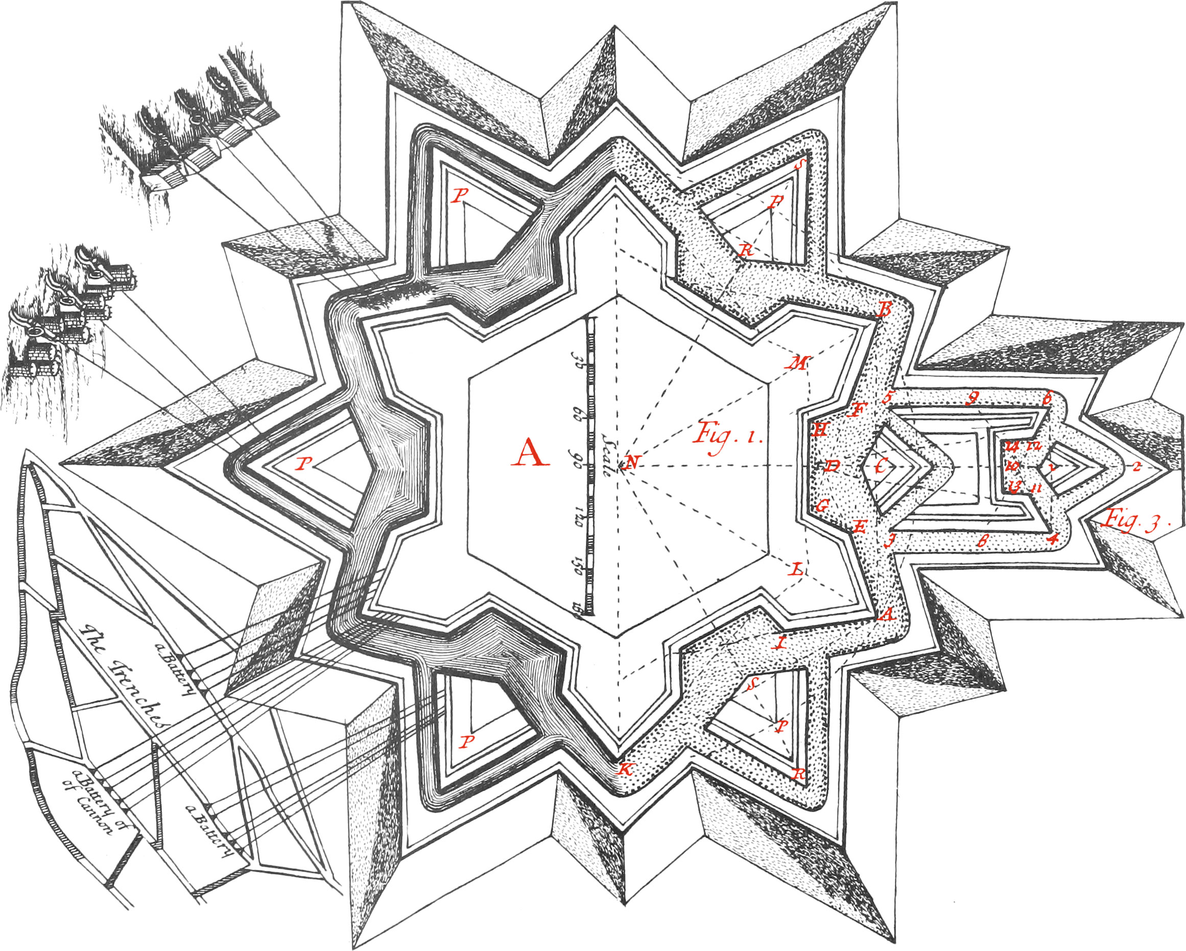
- The Line AB, is called the exterior Side of the Polygon, and LM the interior Side thereof.
- LG the Demi-gorge of the Bastion, of which EG is the Flank, AE the Face, and AL the Capital.
- GH is the Courtain, and AH the Line of Defence Razant.
- The Figure ALGE represents a Demi-Bastion.
- The Angle ANB is the Angle of the Center.
- The Angle KAB is the Angle of the Polygon.
- The Angle IAE, made by the two Faces, is the flanquant Angle, or Angle of the Bastion.
- The Angle AEG made by the Face and the Flank, is called the Angle of the Shoulder.
- The Angle EGH, made by the Flank and the Courtain, is called the Angle of the Flank.
- The Angle EGB, made by the Flank and the Line of Defence, is called the interior flanquant Angle.
- The Angle EDF, made by the two Razant Lines intersecting one another towards the Middle of the Courtain, is called the exterior flanquant Angle, or Angle of the Tenaille.
- The Angle EHG, made by the Courtain and Line of Defence Razant, is called the diminished Angle, which is always equal to that made by the Face of the Bastion and the Base, or exterior Side.
Book IV.
Ch. VIII.
The Uses of the aforesaid Instruments, applied to the Fortification of Places.
Fortification is the Art of putting a Place into such a State, that a small Body of Troops therein may advantageously resist a considerable Arty.
The Maxims serving as a Foundation to the Art of Fortification, are certain general Rules established by Engineers, founded upon Reason and Experience.
The chief Engineer having examined the Extent and Situation of the Place to be fortified, communicates his Design in a Plane and Profil, as may be seen in [in these Figures]. to which he commonly adds a Discourse, orderly explaining the Materials employed by the Undertakers: and having searched the Ground in several Parts of the Place proposed, makes a Computation of each Toise of Work, by means of which the Engineer may nighly estimate the Charge of the whole Work, the Number of Workmen necessary to perfect it, and also the Time it will be done in.
The Plane of a Fortification represents, by several Lines drawn horizontally, the Inclosure of a Place.
This Design contains several Lines drawn parallel to one another; but the first and principal Track, which ought to be marked by a Line more apparent than the others, represents the chief Inclosure of the Body of the Place between the Rampart and the Ditch; so that by the Plan and it’s Scale, the Lengths and Breadths of all the Works composing the Fortification may be known. (Fig. 1.)
The Profil represents the principal Tracks appearing upon a plane Surface vertically cutting and separating all the Works thro’ the Middle. There is commonly a larger Scale to draw it, than to draw a Plan, for better distinguishing their Breadths, Heights, or Depths (as appears in Fig. 3.).
The Names of the chief Lines, and Principal Angles, forming the Plane.
Fundamental Maxims of Fortification.
The principal Maxims may be reduced to fix.
-
Every Side round about a Place, must be flanked or defended with Flanks; for if there be any Side about a Place not seen or defended by the Besieged, the Enemy may there lodge themselves, and become Mailers of the Place in a short time.
It follows from this Maxim, that the flanquant Angle, or the Angle made by the Faces of the Bastion, being too acute, is defective, because it’s Point may easily be blunted or broken by the Cannon of the Besiegers, and afterwards Miners may there work safe in widening of the Breach.
It is also a like Fault to round the Points of Bastions, for the same Reason.
- The Force, as much as possible, must be equally distributed every where, for if there be any Side weaker than the rest, that will be it which the Enemy will attack; therefore if from the Nature of the Ground, one Side be weaker than the others, some Work must be there added to augment it’s Force, in multiplying it’s Defence.
- The flanquant Parts must be no further remote from those which flank them, than a Musquet-shot will do Execution; therefore the Line of Defence, or the Distance from the Point of a Bastion to it’s neighbouring Bastions, ought not much to exceed 125 Toises, which js the Distance that a Musquet, well charged, will do Execution.
- The Flanks of Bastions must be large enough to contain at least 30 Soldiers in Front, and a or 5 Pieces of Cannon mounted on their Carriages, in order to defend well the Face of the Bastion attacked by the Enemy; and since the principal Defence arises from Flanks, it is more proper for them to be perpendicular to the Line of Defence, than to have any other Situation. This Method was assigned by Count Pagan, and has been followed by the ablest Engineers since his Time, and particularly by Monsieur Vauban, who, by his Angular Services, merited the Esteem of all warlike Nations, and able Engineers of his Time.
- The Fortress must not be commanded by any Side out of the reach of Fire-Arms, which are Musquets and Cannon; but, on the contrary, it ought to command all Places round about.
- The Works nighest the Center, must be highest, and command those Places more distant, so that when the Enemy endeavour to make themselves Matters of some Outwork, they may be repulsed by those in the Body of the Place.
To draw upon Paper a fortified Plane, according to the Method of Count Pagan.
Let it be, for Example, an Hexagon: first draw the Line AB 180 Toises, for the exterior Side of the Hexagon, and raise the Perpendicular CD from the Point C of 30 Toises, then draw the Lines ADH, BDG, intersecting each other in the Point D, and take 55 Toises from your Scale, to determine the Length of the Faces AE, BF: from the Point E draw the Flank EG, making a right Angle in the Point G, at the End of the Line of Defence BG, and likewise the other Flank FH at right Angles to AH: finally, draw the Courtain GPI, and you will have one Side of the Hexagon fortified. The other Sides are fortified in the same manner. About this Side of the Polygon thus fortified, you must draw a Ditch, represented by the Lines AC, CB, parallel to the Faces of the Bastions, meeting each other towards the Middle of the Courtain in the Point C. This Ditch ought to be 20 Toises in Breadth, and 3 Toises deep. The Ground taken out in making of the Ditch, serves to form the Rampart with it’s Parapet, and the Glacis of the Covered Way, preserving the finest for the Parapet of the Body of the Place, and the Covered Way; for if the Ground be stony, Cannon-Balls, coming from the Besiegers against Parapets made with it, will make the Stones fly about, and annoy the Soldiers defending the Body of the Place. On the contrary, when the Ground is fine, the Bullets will but make Holes, and enter therein, provided Parapets have Breadth enough to deaden them: by Experience it is found, that Parapets must consist of well-rammed Earth at least 20 Foot thick, to be Proof against Cannon.
The Parapet is made upon the Rampart 24 Feet broad, containing the Banquette, or little Bank, made parallel to the Faces, Flanks, and Courtains, forming the Inclosure of the Place.
The Base of the Rampart is 15 Toises broad, and is made parallel to the Courtains only, to the End that the Bastions may be full, and that there may be there found Earth in case of need, to make an Intrenchment.
When any Bastion is left open, a Mine must be made therein well arched, Bomb proof, and covered with Ground well rammed, and it must be endeavoured to be made so that the Rain-Water cannot get into it, to the End that Provisions put therein, may be preserved from time to time.
The Covered Way is made parallel without the Ditch, about 5 Toises broad, and upon it there is a Parapet made 6 Foot high, and a Banquette, at the Foot of the said Parapet, 3 Foot broad, and a Foot and a half high, so that Soldiers may commodiously use their Arms on the Top of the Parapet, whose Top must be sloped, that is, having a Descent or Slope going down 20 or 30 Toises into the Country.
There must be no hollow Places about this Slope, for the Enemy to cover themselves in; therefore when an Engineer visits the Fortification of a Place, it is requisite for him to examine the adjacent Parts, and have the hollow Places filled up, at least within the reach of a Musquet-shot from the Covered Way; and also to have all Places too high levelled, that so those which defend the Place, may discover all the adjacent Parts.
To draw upon Paper a fortified Plane, according to the Method of Count Pagan.
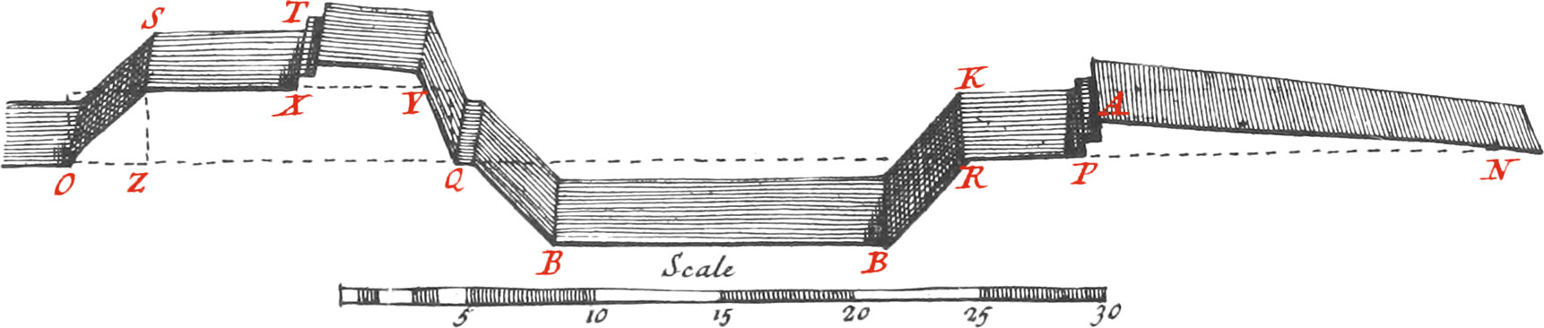
Draw the indefinite Line ON, representing the Level of the Country, and take 15 Toises, which lay off from O to Q, for denoting the Base of the Rampart; then lay off 20 Toises from O to R, for the Breadth of the Ditch, over-against one of the Faces of the Bastion, for it is wider over-against the Courtain: lay off 5 Toises from R to P, for the Breadth of the Covered Way; and lastly, 20 or 30 Toises from P to N, for the Base of the Glacis. Note, The longer the Base of the Glacis is made, the better will it be.
After having determined the Breadths or Thicknesses; the Heights above the Level of the Country, and Depths below, must be as follows.
Take 3 Toises from your Scale, and raise from the Points O, Q, Perpendiculars of that Height, for raising above the Level of the Country the Platform of the Rampart, whereof OS is the interior Talud, or Slope, going up from the City to the Platform of the Rampart ST; which Platform ought to be 6 or 7 Toises broad, that so Cannon may be commodiously used thereon, as also the other necessary Munitions for the Defence of the Place.
Note, The Rising of the Rampart ought to be very easy over-against the Gorge of the Bastions, for Coaches to go easily there up and down it.
The Base of the Talud OZ, is made with new-dug Earth, equal to the Height all along the Courtains; as if the Height be 3 Toises, the Base of the Slope must be also 3 Toises.
But at the Entry of the Bastions, the Base must be at least twice the Height; that is, if the Height of the Slope be 3 Toises, the Base of it must be at least 6 or 8 Toises, for Coaches to go up it.
When the Rampart is formed, and the Earth sufficiently raised upon it, which cannot be done but with Time and Precaution, in well ramming it every 2 Feet in Height, and laying Fascines to keep it together; a Parapet is made upon the Earth of the Rampart, 6 Feet of interior Height, and 4 Feet of exterior Height (for the Top of the Earth to have a Declivity), to discover any thing beyond the Ditch, and being mounted upon the Banquette, the Covered Way may be seen, and defended in case of Need.
The Base of the Parapet XY, ought to be about 4 Toises broad, to the End that the Top thereof may be at least 20 Feet broad. At the Bottom of the interior Slope of the Parapet, there is made a little Bank 3 Feet wide, and a Foot and a half high, so that the Parapet will be 4\(\frac{1}{2}\) Feet above the Bank, which is sufficient for Soldiers to use their Fire-Arms on the Top thereof.
Care must be taken to lay Beds of Fascines every Foot in height, between the Earth of the Parapet; and in order to keep the Earth of the said Parapet from crumbling, it is covered with Grass-Turfs, cut with a Turfing-Iron, from some neighbouring Common, about 15 Inches long, and 10 broad.
Now to lay these Turfs, you must place the first Bed, or Row of them, very level all along the Distance of several Toises, and then lay the Turfs of the second Bed so, that the Joints of the first may be covered with them, and the Joints of the second likewise covered with the Joints of the third, &c. that so they may all make a good joining.
It is sufficient to give 2 Inches of Declivity to one Foot in height, for the interior Slope; and about 4 Inches to one Foot in height, for the exterior Slope of the Parapet. Note, There ought to be Gardiners to cut and lay the Turfs.
At the Foot of the exterior Slope of the Parapet and the Rampart, there is left a little Berm (marked Q, about 4 Feet wide, for retaining the loose Ground falling down from the Slope.
QB represents the inward Slope of the Ditch, which is 3 Toises deep, and BK is the exterior Slope. If the Ground be brittle, they must have more Slope given them, for hindering it’s falling to the Bottom of the Ditch. The Line KP represents the Platform of the Covered Way, which must be 5 Toises broad. PA represents the Parapet of the Covered Way, with it's Banquette at the Foot thereof. The whole must be 6 Feet high, for covering those which are on the Covered Way.
The superior Slope of the Slope AN, ought to be made of fine Earth, the Stones in which, if there be any, must be taken away with an Iron Rake, and buried at the Foot of the Slope, so that Cannon Balls shot from the Enemy upon the Covered Way, may enter therein, without making the broken Pieces of the Stones fly about upon the Covered Way.
To lay off the Plan of a Fortification upon the Ground.
Let, for Example, the Plan of the first Figure be proposed to be drawn upon the Ground.
Instead of a Scale and Compasses, there must be used Staffs, the Toise, and Lines; therefore, after having well examined the Ground, and considered where the Gates and Bastions must be made, which are commonly in the Middle of the Courtains, long Staffs must first be placed, where the flanquant Angles of the Bastions are intended to be.
Now having planted a long Staff upright, in the Place fixed on for the Point of the Bastion (marked A), measure very exactly, with a Toise, or Chain, 90 Toises; at the End of which plant a Staff (marked C): from the Point C continue that Line 90 Toises more; at the End of which plant another Staff, which will be the Point of the Bastion B. In the mean time you are measuring with Chains or Lines, some Workmen must follow, and make a little Trench from Staff to Staff, before the Lines are taken away.
After which, a Perpendicular must be drawn from the Staff C, to the Track ACB.
To draw the said Perpendicular, measure two or three Toises from C to A, where plant a Staff; measure likewise from C towards B an equal Number of Toises, at the End of which plant a second Staff: Take two Lines very equal, and having made Loops in the two Ends of each of them, put those Loops about each of the Staffs, and holding the two other Ends of the Lines in your Hands, stretch them ’till they join upon the Ground, and in their point of Junction plant a third Staff. Lastly, Fasten a Line tight to the Point C, and that third Staff, by which make a Track, which will be perpendicular to the Line ACB.
Measure 30 Toises from the Point C along the Track, at the End of which plant another Staff very upright, which will shew the Point D of the Plan. Return to the Staff A, from which to the Staff D make a Track; along which from the Point A measure 55 Toises towards D, for the Face of the Bastion AE; plant a Staff in the Point E, for denoting the Angle de l’Epaule.
Go to the Point B, and there make the same Operations for drawing the Face BF, and plant a Staff at the Angle de l’Epaule F.
Produce BF from D, towards G; and also AE from D towards H; then measure with the Scale of the Plane the Lines DG, DH, and lay off their Lengths on the Ground from D to G, and from G to H, where plant Staffs: After which it will be easy to draw the Flanks EG, FH, and the Courtain GH.
By this means you will have one Front of a fortified Place, drawn on the Ground; the others may be drawn in the same manner by Staffs and Lines.
Note, It will not be improper to examine with a Semi-Circle, or other such Instrument, whether the Angles drawn upon the Ground are equal to those taken off of the Plane, and to rectify them before the Works are begun.
Care must likewise from time to time be taken, that the Tracks are followed; for without these Precautions there will sometimes happen great Deformities.
Of the Construction of the Outworks.
The Outworks of a Fortification, are those Works made without the Ditch of a fortified Place, to cover it and augment it’s Defence.
The most ordinary kinds of these Works, are the Ravelins or Half-Moons, which are formed between the two Bastions upon the Flanquant Angle of the Counterscarp, and before the Courtain, for covering the Gates and Bridges commonly made in the Middle of the Courtains, as the Figures P P show.
The Ravelins are composed of two Faces furnished with one or two little Banks, and a good Parapet raised on the Side next the Country; and two Demigorges, without a Parapet, on the Side next to the Place, with an Entrance and Slope for mounting the great Ditch on the Platform of the Ravelin.
In each Ravelin there is built a Guard-House, to shelter the Soldiers necessary for it’s Defence, from the Injuries of Weather; but it is proper for the Guard-House to be built in form of a Redoubt, with Battlements all round, for the Soldiers, in case of being attacked, to retire in, and obtain some Capitulation, before they lay down their Arms.
To draw a Ravelin before a Courtain, open your Compasses the Length of the interior Side of the Polygon, and having fixed one of the Points in one of the Ends of the Line, with the other Point describe an Arc without the Counterscarp; likewise set one Foot of the Compasses in the other End of the interior Side, and with the other Point describe a second Arc, cutting the first in a Point, which will be the Point or Flanquant Angle of the Ravelin: then lay a Ruler on the aforesaid Intersection, and upon each of the Ends of the interior Side of the Polygon, for drawing the Faces of the Ravelin, which will terminate to the Right and Left upon the Edge of the Counterscarp. The two Demigorges are drawn from the End of each Face, to the Rentrant Angle of the Counterscarp.
But that the Flanquant Angle may not be too acute, it’s Capital RS must be but about 40 Toises; and proceed with the rest, as before.
Sometimes a similar Work is made before the Point of a Bastion; and since it’s Gorge is built upon the Edge of the Counterscarp, which is commonly rounded over-against the Point of the Bastions, this Work is called a Half-Moon (because it’s Gorge is in the Form of an Arc): They are very often confounded, and the greatest Part of the Soldiers give, without distinction, the Name of Half-Moons to Ravelins made before the Courtains.
The Defect of this Work is, that it is too distant from the Flanks of the Bastions, for being sufficiently defended by them; therefore a Half-Moon must not be made before the Point of a Bastion, unless at the same time there are made other Out-Works to the Right and Left before the adjacent Courtains, to defend it.
It is proper for these Works to be lined with Walls, as well as the Body of the Place; for when they are rot, the Ground must have so great a Slope, that it will be easy to mount the Works.
In the mean time the new-dug Earth the Works are made with, must settle at least a Year or two before the Walls are built, to the End that the Walls may not be thrown down by it after they are built.
These kind of Works are commonly made before the Courtains, and because the Expence in making them is greater than the Expence in making the Ravelins, they are not made without absolute necessity; they serve to cover some Side of the Place, weaker than the others; they likewise serve to occupy an Height, which cannot be done by Persons inclosed in the Body of the Place.
Now to draw a Hornwork, first raise the Indefinite Perpendicular 1, 2, on the Middle of the Courtain; and to this Line draw two Parallels 3, 4, and 5, 6, from the Angles of the Shoulders. These two Parallels, which are called the Wings of the Hornwork, ought to draw their defence from the Faces of the Bastions; whence their Length ought not much to exceed 120 Toises, counting from the Shoulders. Thro’ the Ends of the Wings draw the Line 4, 6, which will be the exterior Side of the Hornwork, and is divided into two equal Parts in the Point 7, by the Perpendicular 1, 2; then take half that exterior Side in your Compasses, and lay it off upon the Sides, from 4 to 8, and from 6 to 9; draw the Lines 4, 9, and 6, 8, which intersecting one another in the Point 10, will form the Angle of the Tenaille, that represents a Work called the Simple Tenaille, which is common enough made before the Courtains, with a little Ravelin without the Ditch, between the two Saliant Angles, and over-against the Middle of the Rentrant Angle.
But to to strengthen this Work, there is added thereto two Demi-bastions, and a Courtain between them; which is better than two simple Rentrant Angles.
To draw the Demi-bastions, bisect the Line 4, 10, in the Point 11; and likewise the Line 10, 6, in the Point 12; then from the Points 11 and 12, draw to the Middle of the Courtain of the Place, as at the Point 1, the occult Lines 121, 111, by which means will be had the little Courtain 1314 of the Hornwork, the two Flanks 1113, 1214, and the two Faces 114, 126.
The Sides of these Works, which are next to the Country (as the Demi-bastions, the Courtain, and the Wings of the Hornwork are), ought to be furnished with a good Parapet of fine Earth well rammed, 18 or 20 Feet thick, and 6 Feet high before, containing a Banquette, like that in the Body of a Place; observing at all times, that the Parapets of the "Works nigher the Center of the Place, must be higher above the Level of the Country, than those Works more distant; to the End that when the Besiegers have made themselves Masters of some Outwork, the Besieged, defending the Body of the Place, seeing them altogether uncovered, may dislodge them therefrom.
These Parapets ought to be sustained by a Rampart, whose Platform having a Banquette, is three or four Toises wide; but when Earth is wanting, we must be content to make several little Banks upon one another eighteen Inches high, and three or four Feet broad; and the Parapet ought to be about 4\(\frac{1}{2}\) Feet above the highest Bank, for covering the Soldiers: the Top of the Parapet must be sloped, gradually descending towards the Country, so that the Besieged may see the Enemy.
The parts of those Works, which are next the Place, must be without a Parapet, and only inclosed with a single Wall, or a Row of Palisadoes, to avoid the Surprizes of the Enemy. It is on this side that a Gate must be (for a Communication from the Works to the Body of the Place); as also a Guard-House, for covering the Soldiers designed for it’s defence.
All these Works ought to be environed with a Ditch 10 or 12 Toises broad, communicating with the Ditch of the Body of the Place, and also as deep.
On the outside of that Ditch is made a Covered Way five or six Toises broad, with a Parapet, and it’s Bank, commonly furnished with an enclosure of strong Palisadoes, drove 4 or 5 Feet into the Ground. The Top of that Parapet must be sloped next to the Country, and if it can be produced 20 or 30 Toises it will be better: for a Slope (or Glacis) cannot be too long; because, by means thereof, the Enemy cannot approach the Body of the Place, without being discovered.
The Outworks of which we have spoken, are the most common ones: There are many other sorts of them, which we shall not mention, it requiring a great Volume.
How to measure the Works of Fortifications.
The Ground of which the Ramparts and Parapets are formed, is generally taken out of the Ditches made about the Place; to know the Quantity of which, measure the Cavity of the Ditches, and reduce it to Cubic Toises. As, for example, If the Ditch over-against the Face of a Bastion, be 50 Toises long, 20 broad, and 4 deep; multiply the Length by the Breadth, and the Product will be 1000 square Toises, which multiplied by 4 the Depth, and there will arise 4000 Cubic Toises.
Note, That since there is a Necessity to give the Ground a great Slope, to keep it from crumbling to the Bottom, the Ditch will be wider at the Top than at the Bottom; whence, if a Ditch be 20 Feet broad in the Middle of it’s Depth, at the Top it must at least be 22 Toises broad, and 18 Toises at the Bottom: Those 22 Toises added to 18, make 40, whose half 20, is the mean Breadth to be used.
The Stone, or Brick-work, keeping together the Earth, ought to have thickness proportionable to it’s height, and also about a Foot in Talud or Slope, the Height of every Toise.
If, for Example, a Wall be built to sustain the Earth of the Rampart of a Place, and it is 6 Toises high, the least thickness that can be given to that height, at the Top, must be 3 Feet, and at the Bottom, just above the Foundation, 9 Feet, because of it’s Talud of 1 Foot every Toise in height: Now these two thicknesses, 9 and 3 make 12, whose half 6 Feet is the mean thickness of the Wall; and, consequently, to line the Face of a Bastion, 50 Toises long, 6 Toises high, and one Toise of mean thickness, there must be 300 Cubic Toises of Walling, excluding the Foundation, which cannot be determined without knowing the Ground. Besides this, there are commonly made Counter-Forts for sustaining the Earth, and hindering it’s pressing too much against the Walls. These Counter-Forts ought to be sunk in firm Ground, and enter in the dug Earth, at least a Toise; they are 7 or 8 Feet broad at the Root, that is, on the Side where they are fastened to the Wall, and 4 or 5 Feet at the End, going into the Earth of the Rampart, which amounts to one Toise of Surface, in supposing (as we have already) that the Root is 7 Feet, and the End going into the Earth of the Rampart 5 Feet, which makes 12 Feet, half of which being 6, is the mean thickness; and supposing them 4 Toises in height, one with another, each will be 4 Cubic Toises: and since there ought to be 10 in the Extent of 50 Toises, the Stone, or Brick-Work of 10 Counter-Forts will be 40 Cubic Toises: So that there will be about 1000 Cubic Toises to wall the two Faces, and the Flanks of a Bastion, and to wall a Courtain, 80 Toises in length, there must be about 600 Cubic Toises of Stone, or Brick-Work; whence the Walling for the whole Place may be easily computed.
Note, It is better to make an Estimation too great, than too little.
It remains that we say something of the Carpenters Toise, required to construct Bridges and Gates, and other Works of the like Nature.
In measuring of Timber, we reduce it to Solives.
A Solive is a Piece of Timber 12 Feet long, and 36 Inches in surface; that is, 6 Inches broad, and 6 thick, which makes 3 Cubic Feet of Timber, being the seventy second Part of a Cubic Toise.
We shall give here two Ways of Calculation, to the End that the one may prove the other.
The first is, to reduce the Bigness of the Piece of Timber into Inches, that is, the Inches of it’s Breadth and Thickness, and after having multiplied these two Quantities by one an other, the Product must be multiplied by the Toises, Feet and Inches of it’s Length, which last Product being divided by 72, the Quotient will give the Number of Solives contained in the Piece of Timber.
The Reason of this is, because 72 Pieces, 1 Inch Base, and a Toise long, make a Solive.
Suppose, for Example, a great Piece of Timber is to be reduced to Solives, whose length is 2 Toises, 4 Feet, 6 Inches, and 12 by 15 Inches Base; multiply 15 by 12, the Product is 180 square Inches, which again multiplied by 2 Toises, 4 Feet, 6 Inches, and the Product 495, divided by 12, will give 6\(\frac{7}{8}\) Solives.
The second Method is founded upon this, that a Solive contains 3 Cubic Feet.
As, for Example, If a Piece of Timber (the same as before) be 2 Toises, 4 Feet, 6 Inches long, and Base be 12 by 15 Inches; multiplying 12 by 15, the Product will be 180 square Inches; the 12th Part of that Number, which is 15, being considered as Feet, makes 2 Toises 3 Feet, which, multiplied by the Length 2 Toises, 4 Feet, 6 Inches, make 6 Solives, 5 Feet, and 3 Inches: So that there wants but 9 Inches, or the eighth Part of a Toise, to make 7 Solives, as in the Calculation of the first Method.