The Description of a Second-Pendulum-Clock for Astronomical Observations.
Fig. 1
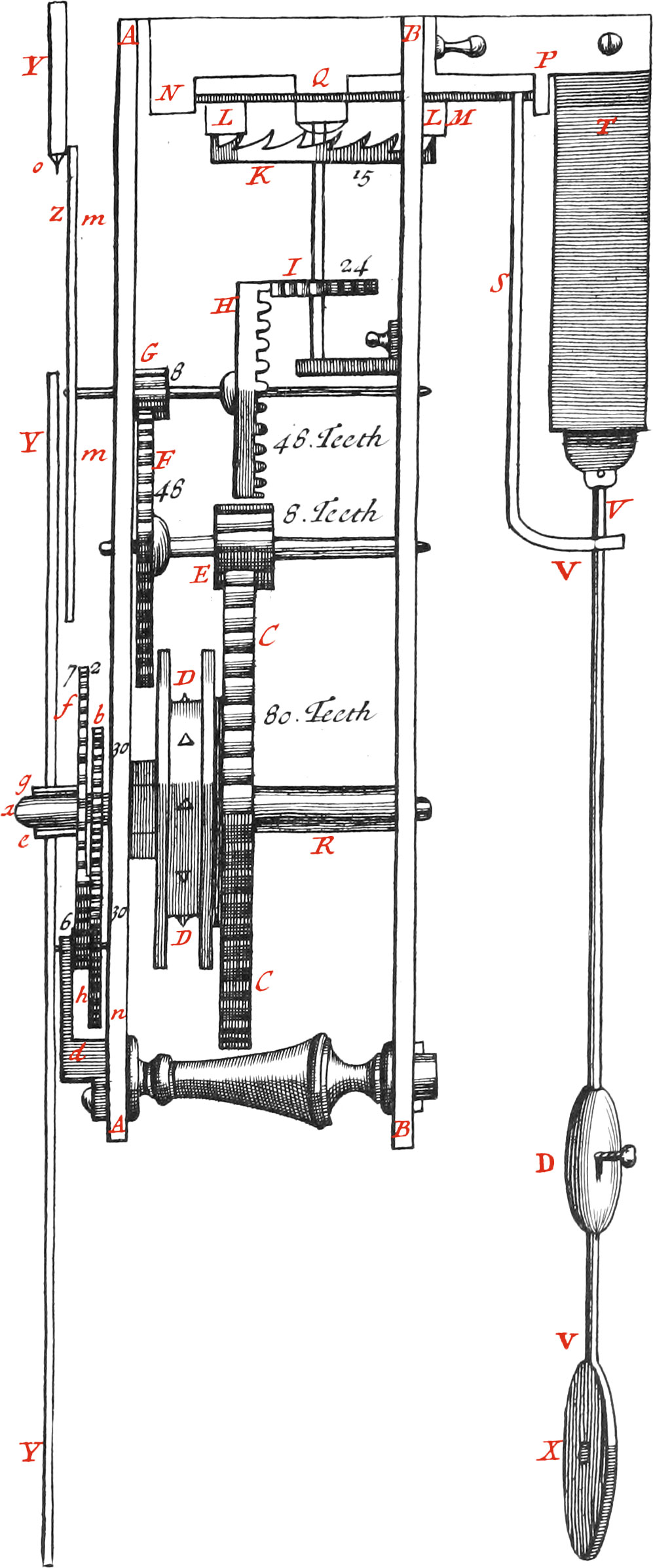
Figure here adjoined, shews the Composition of a Second-Pendulum-Clock, whose two Plates AA and BB, are about half a Foot long, and two Inches and a half broad, having four little Pillars at the four Corners, that so they may be an Inch and a half distant from each other. These Plates serve to sustain the Axes of the principal Wheels, the first of which being the lowest, and figured CC, hath 80 Teeth. The Axis of this Wheel hath a little Pulley, having several Iron Points DD round about the same, in order to hold the Cord to which the Weights are hung, in the manner as we shall explain by and by. The Wheel CC, being turned by the Weight, likewise turns the Pinion, E of eight Teeth, end so moves the Wheel F, which is fastened to the Axis of the Pinion E; this Wheel hath forty-eight Teeth, which falling into the Teeth of the Pinion G, whose Number is eight, moves the Wheel H, (made in figure of a Crown) confiding of forty-eight Teeth. Again, The Teeth of this last Wheel fall into the Teeth of the Pinion I, whose Number is twenty-four, and the Axis thereof being upright, carries the Wheel K of 15 Teeth, which are made in Figure of a Saw: Over this Wheel is a cross Axis, having two Palats LL, sustained by the Tenons N, Q and P, which are fastened to the Plate BB. It must be observed, that as to the Tenons N and Q, the lower part Q appearing, hath a great Hole drilled therein, that the Axis LM may pass thro’ it; this part Q, which is fastened to the lower part of the Tenon N, likewise holds the Wheel K, and the Pinion I. There is a great Opening in the Plate BB, in order for the Axis and the Palats to go out beyond it. One end of this Axis (as I have already mentioned) goes into the Tenon, P, and so moves easier than if it was sustained by the Plate BB, and then go out beyond the said Plate, which it must necessarily do, that so the little Stern S, fixed thereto, may freely vibrate with the said Axis, and the Teeth of the Wheel K alternately meet the Palats LL, as in common Clocks.
Fig. 2
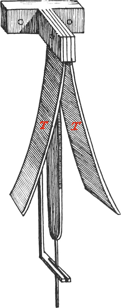
The lower part of the little Stern S is bent, and a slit made therein, thro’ which goes an Iron-Rod, serving as a Pendulum, having the Lead X at the End thereof. This Rod is fastened in V to a very thin Piece of Brass or Steel, which vibrates between two cycloidal Cheeks TT, (one of which is seen in Fig. 1, and both in Fig. 2.) of which more hereafter.
It is easy to perceive in what manner this Clock goes by the Force of the Wheels carried round by the Weight: for the Motion is continued by the Pendulum VX, when the said Pendulum is set a-going; because the little Stern S, altho’ very light, being in motion, not only goes with the Pendulum, but likewise by its Vibrations still assists the Motion some small matter, and so renders it perpetual, which otherwise by Friction and the Air’s resistance, would come to nothing. But because the Property of the Pendulum is to move equably always, provided its length be the same, the said Pendulum will cause the Wheel K to go neither too fast nor too slow, (as happens to Clocks not having Pendulums) every Tooth is Obliged to move equably; therefore the other Wheels, and the Hands of the Dial-plate, are necessarily constrained to perform their Revolutions equably. Whence if there should be some Default in the Construction of the Clock, or if the Axes of the Wheels do not move freely on account of the Intemperance of the Air, provided the Clock does not stand still; we have nothing to fear from these Inequalities, for the Clock will always go true.
As to the Hands for shewing the Hours, Minutes, and Seconds, we dispose them in the following manner. The third Plate YY is parallel to the two precedent ones, and is three Lines distant from AA. We describe a Circle about the Center a, which is the middle of the Axis, carrying the Wheel C, continued out beyond the Plate AA. This Circle is divided into 12 equal Parts, for the Hours. We likewise describe another Circle about the said Center, and divide it into 60 equal Parts, for the Minutes in an Hour. We place the Wheel b upon the Axis R, continued out beyond the Plate AA, fastened to a little Tube, going out beyond the Plate YY to e. This Tube is put about the Axis R, and turns about with it, in such manner nevertheless, that it may be turned only when there is necessity. We place the Hand shewing the Minutes in e, which makes one Revolution in an Hour. The beforementioned Wheel b moves the Wheel h, having the same Number of Teeth as that, viz. 30; and the Teeth of the Wheel f, falls into the Teeth of the Pinion h, whose Number is 6, and they have a little Axis common to them, which is partly sustained by the Tenon d. This Pinion moves round the Wheel f, having 72 Teeth, fastened to a little Tube g, which is put about the Tube carrying the Wheel b. Now the Hand shewing the Hours must be placed upon the Extremity of the Tube, and will be shorter than that denoting the Minutes. But that one may not be deceived in reckoning of Seconds, we place a round Plate mm upon the Extremity of the Axis of the Wheel H, divided into 60 equal Parts, and make an opening Z in the Plate Y, in the upper Part of which Opening is a small Point o, which, as the said Plate turns about, shews the Seconds. The Disposition of the Hands and Circles will be easier seen in Figure 3, which represents the Outside of the Clock.
Now having spoken of the Disposition of the Wheels, the next thing is to determine the Length of the Pendulum, which must be such, that every of its Vibrations be made in a Second of Time. This Length must be 3 Feet 8\(\frac{1}{2}\) Lines (of Paris1) from the Point of Suspension, which is the Center of the cycloidal Cheeks, to the Center of the Weight X.
We now proceed to say something concerning the Times of the Revolutions of the Wheels and the Hands, in order to confirm what we have already said of the Number of Teeth. Now one Revolution of the Wheel CC, makes ten Revolutions of the Wheel F, sixty of the Wheel H, and one hundred and twenty of the upper Wheel K, which having 15 Teeth, and alternately pushing the Palats LL, makes thirty Vibrations, which are so many goings and comings of the Pendulum VX. Whence 120 Revolutions of the Wheel K, is equal to 3600 Vibrations of the Pendulum, which are the Seconds contained in one Hour; and so the Wheel C makes one Revolution in an Hour, and the Hand e fastened thereto, shews the Minutes; and because the Wheel b makes it’s Revolution in the same time, (viz. an Hour) the Wheel h hath the same Number of Teeth as b, and the Pinion on the same Axis hath six Teeth j and since the Number of Teeth of the Wheel/ is twelve times greater, the said Wheel will go round once in 12 Hours, as likewise the Hand g fastened thereto. Finally, Because the Wheel H is making sixty Revolutions in the same time the Wheel CC is making one, therefore the circular Plate Z, having the Seconds denoted thereon, will move once round in a Minute; and so every 60th part of the said Plate will shew one Second.
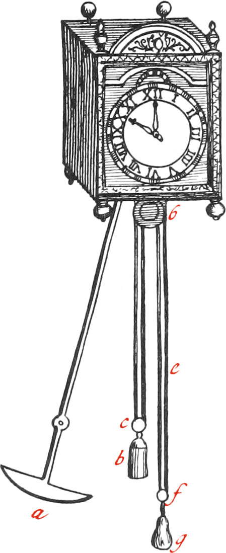
The Weight X, at the end of the Pendulum, must weigh about 3 Pounds, and be of Lead covered with Brass. Regard must not only be had to its Weight, but likewise to its Figure, which is of Consequence, because the least Resistance of the Air is prejudicial thereto; whence We make it in form of a Convex Cylinder a, whose ends are pointed, as appears in Figure 3. wherein the Pendulum is represented, tho’ the Weights at the end of the Pendulums made for these Clocks used at Sea are in the Figure X, in form of a Lens, this Figure being found more proper than the other.
Fig. 3
In the same Figure may likewise be seen the manner of the Disposition of the Weight b, in order to so move the Clock, that it may not stand still while the Weight b is drawing up; and this is done by means of a Cord, one end of which must first be fastened to a piece of Iron fixed to the Plate AA, (of Figure 1.) and then it must be put about the Pulley c, of the Weight b; afterwards over the Pulley d, (which hath Iron Points round it in figure of the Teeth of a Saw, for hindering, left the Weight b should pull the Cord down all at once) then about the Pulley f of the Weighty, and last of all the other end of the said Cord must be fixed to some proper Place. Things being thus disposed, it is manifest that half of the Weight b moves the Wheels round, and that the Motion of the Clock doth not cease, when the Cord e is pulled with one’s Hand in order to draw the Weight b up. Note, The Weight g is for sustaining the Weight b, and need not be near so big.
The Weight of b cannot be certainly determined by Reasoning, but the less it is the better, provided it be sufficient to make the Clock go. They weigh generally about six Pounds in the best Kind of these Clocks that have yet been made, whereof the Diameter of the Pulley D is one Inch, the Weight of the Pendulum X three Pounds, and it’s Length three Feet 8\(\frac{1}{2}\) Lines. Note, If this Clock be at the Height of a Man above the Ground, it will go 30 Hours.
Fig. 4
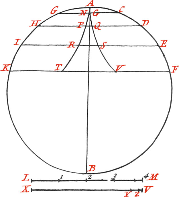
We now proceed to shew the Manner of making the Cycloidal Cheeks between which the Pendulum swings, and in which the whole Exactness of the Clock consists. In order to do which, describe the Circle AFBK, whose Diameter AB let be equal to half of the Length of the Pendulum; assume the equal Parts of the Circumference AC, CD, DE, EF and AG, GH, HI, IK, and draw the Lines GC, HD, IE and KF, from one Division to the other, which Lines will be parallel. Now make the Line LM equal to the Arc AF, which divide into the same Number of equal Parts as AF, and assume one of these Parts, which lay off upon the Line CG, from C to N, and G to O. Again, Lay off two of the said equal Parts of the Line LM, upon the Line DH, from D to P, and from H to Q. Moreover, Assume three of the said equal Parts upon the Line LM, which lay off upon IE from E to R, and I to S. And finally, Assume four of the said Parts (which is the whole Length of the Line LM), and lay off upon KF, from F to T, and K to V; and so of other Parts, if there had been more of them assumed upon the Periphery of the Circle AFBK. Now if the Points N, P, R, T, as also O, Q, S, V, be joined, we shall have the Figure of the Cycloidal-Cheeks (between which the Pendulum swings), which must be afterwards cut out in Brass. To draw the Line LM equal to the Arc AF, assume the two Semi-Chords of the Arcs AF, which lay off upon the Line XV, from X to Y; this being done, take the whole Chord of the Arc AF, and lay off from X to Z, and divide ZY into three equal Parts; one of which being laid off from Z to V, and the Line XV will be nearly the Length of the Arc AF.
The Use of this Instrument sufficiently appears from what hath been already said.
The principal Instruments that an Astronomer ought to have, besides a good Quadrant, and Pendulum Clock, is a Telescope seven or eight Feet long, having a Micrometer adjusted thereto, for observing the Digits of Solar and Lunar Eclipses, as likewise another of 15 or 16 Feet, for the Observation of Jupiter’s Satellites; and, if possible, a parallactick Instrument to take the Parallaxes of the Stars.
1Or 3 Feet 9\(\frac{1}{3}\) Inches of our English Measure.