Mathematical Instruments
Book VIII. Ch. IV.

Of the Construction and Uses of Instruments for drawing Dials upon different Planes.

Fig. 8

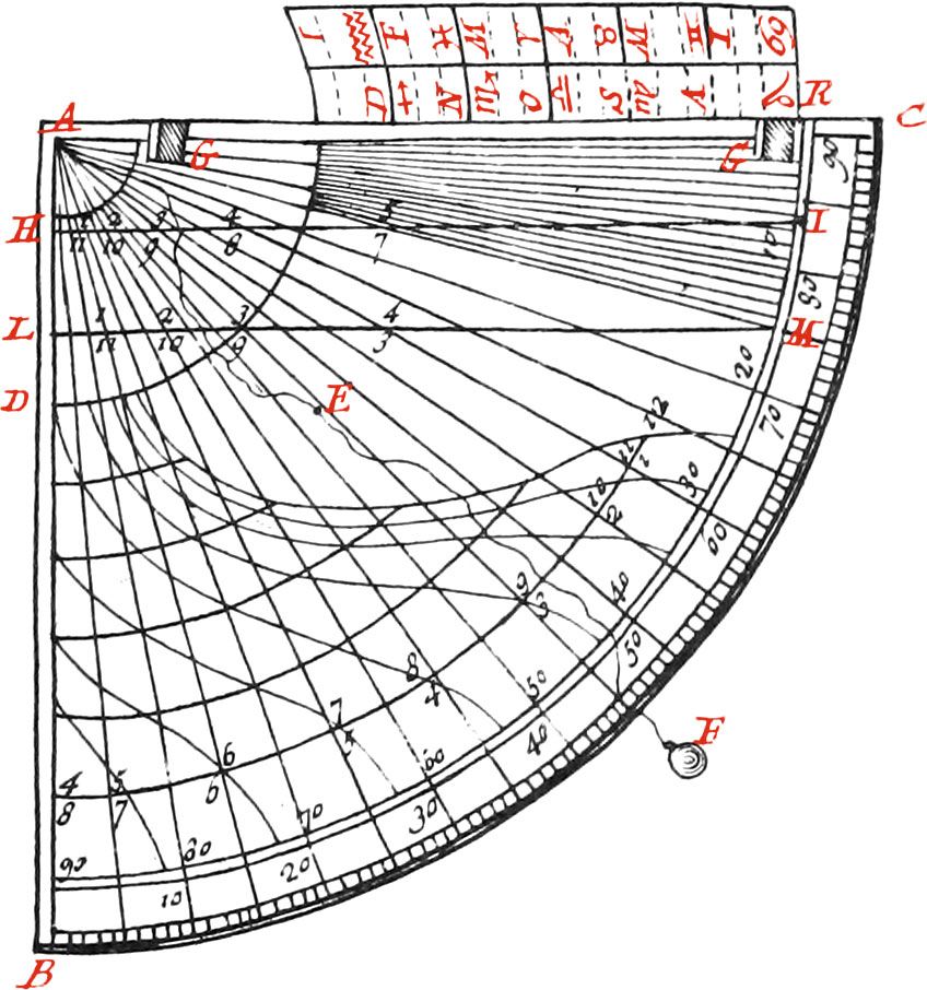
The eighth Figure represents a Quadrant made of Brass or any solid Matter, of a bigness at pleasure, having the Limb divided into 90 Degrees. The Use of this Quadrant may be to find the Lengths of Tangents, and by this means to divide a right Line into Degrees, as we did the Meridian of the horizontal Dial (Fig. 7.) we may find likewise thereon the Divisions of the Equinoctial Line thro’ which the Hour-Lines must pass, in regular Dials; as also in declining Dials, if the Substyle falls exactly upon a compleat Hour-Line, by laying off the Length of the Radius of the Equinoctial Circle, from the Center A to H or L, and drawing a right Line, as HI or LM, parallel to the Radius of the Quadrant AC. For example, the Length L1 or n, answering to 15 Deg. of the Quadrant, shall be the Tangent of the first Hour-Line’s distance from the Meridian or Substyle of the Dial, which being laid off upon the Equinoctial Line, whose Radius is supposed equal to AL, will determine a Point therein thro’ which the said Hour-Line must be drawn. L12, answering to 30 Deg. of the Limb of the Quadrant, will be the Tangent of the second Hour-Line's distance from the Meridian or Substyle. L3, the Tangent of 45 Deg. will be that of the third, and so on. Now if by this means you draw the Hour-Lines of three Hours successively on each side the Meridian or Substyle, which in all make six Hours successively; these are sufficient for finding the Hour Lines of the other Hours, according to the Method before explained in speaking of declining Dials, and which may be even applied to all regular Dials. For example, If the Hour-Lines of six Hours successive be drawn upon an horizontal Dial, as, from 9 in the Morning to 3 in the Afternoon, you may draw all the other Hour-Lines of the Dial by the aforesaid Method; as the Hour-Lines of 7 and 8 in the Morning, and 4 and 5 in the Afternoon, whose Points in the Equinoctial Line are sometimes troublesome to be pricked down, and principally the Points of the Hour-Lines of 5 and 7, because of the Lengths of their Tangents.

The Hour-Lines found by the abovesaid Method, which we shall not here repeat, will serve for finding of others; and these which are last found being produced beyond the Center, will give the opposite ones.

The said Quadrant will serve moreover as a portable Dial, since the Hour-Lines may be drawn upon it by means of a Table of the Sun’s Altitude above the Horizon of the Place for which the Dial is to be made. See more of this in the next Chapter.

The Construction of a moveable horizontal Dial.

Fig. 9

This Instrument is composed of two very smooth and even Plates of Brass, or other solid Matter, adjusted upon each other, and joined together by means of a round Rivet in the Center A. The undermost Plate is square, the Length of the Side thereof being from 6 to 8 Inches, and is divided into twice 90 Degrees; by means of which, the Declinations of Planes may be taken. The upper Plate is round, being about 8 Lines shorter in Diameter than is the Length of the Side of the under Plate, and having a little Index joined to the Hour-Line of 12, shewing the Degree of a Plane’s Declination.

About the Center A is drawn an horizontal Dial upon the upper Plate, for the Latitude of the Place it is to be used in, and the Axis B is so adjusted, that the Point thereof terminates in the Center A, wherein a small Hole is made for a Thread to come thro’. There is also a Compass D fastened to this upper Plate, having a Line in the Bottom of the Box, shewing the Variation of the Needle.

The Use of the moveable horizontal Dial.

The Use of this Instrument is for drawing Dials upon any Planes, of whatsoever Situations (as on declining inclining Planes, or both) in the following manner:

First draw a Horizontal or level Line upon the proposed Plane; place that side of the Square along this Line, whereon is wrote the Side applied to the Wall, and turn the horizontal Dial ’till the Needle settles itself over the Line of Declination in the Bottom of the Box: then extend the Thread along the Axis of the Dial ’till it meets the Plane, and the Point wherein it meets the said Plane will be the Center of the Dial. This being done, extend the Thread along each of the Hour-Lines of the horizontal Dial that the Plane can receive, and mark the Points on the horizontal Line upon the Plane, cut by the Thread: then if Lines be drawn from the Center found on the Plane thro’ each of those Points, those will be the respective Hour-Lines that the Thread was extended along on the horizontal Dial, and must have the same Figures set to them. Note, If the Dial be vertical, not having any Declination, the Hour-Line of 12 will be perpendicular to the horizontal Line of the Plane.

The substylar Line is drawn thro’ the Center of the Plane, and the Angular Point of a Square, one Side whereof being laid along the horizontal Line, and the other Side touching the Style of the horizontal Dial.

Again, The Distance from the Side of the Square laid along the Plane to the Axis, is the Length of the right Style, which being laid along in the same Place at right Angles to the Substyle, you may draw the Axis from the Center to the Extremity thereof; which may be formed on the Plane by means of an Iron Rod, parallel to the Situation of the Thread extended along the Axis of the horizontal Dial, and must be sustained by a Prop planted in the Plane perpendicular to the Substyle.

If you have a mind to have a right Style only, some Point must be sought in the Substyle distant from the Center of the Dial, proportional to the Bigness of the Dial, and an Iron-Rod must be set up perpendicularly therein: but the Point of this Rod must touch the Thread extended along the Axis. Finally, You may give what Figure you please to the Dial, and produce the Hour-Lines as is necessary, according to the bigness of the Plane. If a great Dial is to be drawn, you may place the Instrument at a Distance from the Plane it is to be drawn on; but then you must take care that it be very level, and the Side thereof parallel to the Plane. And if North Dials are to be drawn, having first found the Declination of the Plane, for Example, 45 Deg. North-westwardly, place the Index of the Dial over the Degree of the opposite Declination on the square Plate, viz. over 45 Deg. South-east-wardly, then invert the whole Instrument, and extend the Thread along the Axis, that so the Center of the Dial may be found upon the Plane underneath the horizontal Line, on which having pricked down the Points thro’ which the Hour-Lines must pass, you may draw them to the Center, and then proceed as before.

The Construction of Sciaterra.

Fig. 10

This Instrument is composed of an Equinoctial Circle A, made of Brass or any other solid Matter, adjusted upon a Quadrant B. The Point of the Hour of 12 of this Equinoctial Circle is fastened to one end of the Quadrant, and a little Steel Cylinder about two Lines in Diameter, serving for an Axis, and going thro’ the Center of the Equinoctial Circle, is so fixed to the other End C of the Quadrant, as to keep the said Equinoctial Circle fixed at right Angles to the Quadrant.

The Quadrant is divided into 90 Deg. and is made to slide on the Top of the Piece L, according to different Elevations of the Pole. The little Ball G is hung at the End of a Thread, whose other End is fastened to the Top of an upright Line on the Piece L, and so by means of this, and the Ball and Socket H, the Instrument may be set upright. The Piece I is of Steel, and the End thereof is forced into a Wall or Plane, to support the whole Instrument when it is to be used. The Figure D is the Trigon of Signs put on the Axis, and turns about the same by means of a Ferril. This Trigon has a Thread F fastened to the Extremity thereof, and there is another Thread F fastened, to the Center of the Dial. But note, We do not place the Trigon upon the Axis, unless when the Arcs of the Signs are to be drawn upon Dials.

The Use of the Sciaterra.

You must first force the Steel Point I, into the Wall or Plane whereon a Dial is to be drawn, and place the Quadrant to the Degree of the Elevation of the Pole: then you must take a Square Compass, and lay the Side thereof along the Plane of the Quadrant, and turn the Instrument until the Needle fixes itself directly over the Line of Declination; or if you have not a Compass when the Sun shines, and the Hour of the Day is known, turn the Instrument ’till the Shadow of the Axis falls upon the Hour of the Day upon the Equinoctial Circle.

The Instrument being thus disposed, extend the Thread E from the Center along the Axis ’till it meets the Wall or Plane proposed, and there make a Point for the Center of the Dial: then extending the said Thread over each Hour of the Equinoctial, note the Points wherein it meets the Wall or Plane, and draw Lines from the Center (before found) thro’ them, and those will be the Hour-Lines. After this, you may give the Dial what Figure you please, and set the same Figures upon the Hour-Lines as are upon the correspondent Hours of the Equinoctial Circle. Note, The Style is set up in the manner we have mentioned in speaking of the moveable horizontal Dial.

If the Arcs of the Signs, or diurnal Arcs, are to be drawn upon the Dial, you must put the Ferril at the End of the Trigon upon the Axis, and fix it over each Hour of the Equinoctial one after another by means of the Screw: then extending the Thread F along the Lines appertaining to each Sign, mark as many Points on each Hour-Line on the Wall or Plane, and join them by curve Lines, which shall form the Arcs of the Signs, whereon must be set their respective Characters.

The Arcs of the Signs may be otherwise drawn in the following manner: The Axis of the Dial being well fixed, chuse a Point in the same for the Extremity of the right Style, representing the Center of the Earth; and upon this Axis put the Ferril of the Trigon in such manner, that the Extremity of the right Style exactly answers to the Vertex of the Trigon, representing the Center of the Equinoctial and the World. Then having fixed the Trigon by means of the Screw pressing against the Axis, turn it so that one of the Planes thereof (for the Signs ought to be drawn upon both sides) falls exactly upon the Hour-Lines one after another, and extend the Thread F along the Radius’s of the Signs on the Trigon, and by means thereof mark Points upon each Hour-Line of the Wall or Plane: and if these Points be joined, we shall have the Arcs of the Signs.

Proceed thus for drawing North Dials, as likewise inclining and declining Dials, in observing to invert the Instrument when the Centers of the Dials are downwards.

The Construction of M. Pardie’s Sciaterra.

Fig. 11

This Instrument, which is made of Brass or other solid Matter, of a Bigness at pleasure consists of four principal Pieces or Parts. The first is a very even square Plate D, called the horizontal Plane, because it is placed horizontal or level when using, having a round Hole E in the Middle, wherein is placed a Pivot, upon which turns the second Piece, called the meridional Plane, in such manner that the said Piece is always at right Angles to the horizontal Plane. On the narrow Side C of this Piece is fastened a Plumb-Line, whose use is for placing the Instrument level. The Top of this Piece is cut away into a concave Quadrant, both sides of which are divided into 90 Deg. beginning from the Perpendicular answering to the Middle of the Pivot, and there is a pretty deep Slit made down the Middle of this Quadrant to receive a prominent Piece of a Semi-Circle H, which is the third principal part, that so the said Semi-Circle may be in the same Plane as the second Piece is, and likewise be raised or lowered according to different Elevations of the Pole. The Diameter of this Semi-Circle is called the Axis, and the Center thereof is simply called the Center of the Instrument, like as the Thread fastened thereto is called the centeral Thread. The fourth Piece A is a very even Circle, both sides thereof being divided into 24 equal Parts, for the 24 Hours of the Day; and this is fixed at right Angles to the Semi-Circle H, and so moves along with it. One of the Sides thereof is called the upper-side, and the other the under-side. The Trigon of Signs is drawn (in the manner before explained) upon both sides of the Semi-Circle, having the Point A, the Extremity of the Diameter of the Equinoctial Circle, for the Vertex thereof.

The Use of this Instrument.

Having first placed the Points of ♈︎ and ♎︎ of the Semi-Circle upon the Degree of the Elevation of the Pole in the Place for which you would draw a Dial, set the Instrument upon a fixed horizontal Plane, near to the Wall or Plane you are to draw a Dial on. Then turn the Meridional Plane ’till the Shadow of the Equinoctial Circle falls upon the Day of the Month or Degree of the Sign on the Axis the Sun is in. This being done, the Shadow of the said Axis or Diameter of the Semi-Circle H, will shew the Time of Day upon the Equinoctial Circle, and the whole Instrument will be well situated, the Meridional Plane answering to the Meridian of the Heavens, the Equinoctial Circle parallel to the Celestial Equinoctial Circle, and the Axis of the Dial parallel to the Axis of the World. This being done, extend the Thread F fastened to the Center, along the Axis to the Wall or Plane you are to draw a Dial on, and the Point wherein it meets the Wall will be the Center of the Dial. The said Thread thus extended will likewise give the Position of the Style or Axis of the Dial; for if an Iron Rod be placed in the said Point of Concourse, and in the same Situation as the Thread is, this will be the Style of the Dial: but if you have a mind to have a right Style only, you need but set up a Rod in the Wall or Plane, whose end touches the Thread extended along the Axis of the Instrument; and this Rod may have what Figure you please given to it, as a Serpent or Bird, provided the Extremity of the Bill thereof meets the said Thread.

Now to mark the Hour-Lines upon the Dial, extend the Thread from the Center over the Plane of the Equinoctial Circle along the Hour-Lines thereof one after another, until it meets the Wall: then if Lines be drawn from the Center of the Dial to the said Points of Concourse, these will be the Hour-Lines. But the Hour-Lines may be otherwise pricked down in the Night, by the light of a Link or Candle; for the centeral Thread being first extended along the Axis, and fastened to the Wall, afterwards move the Link ’till the Shadow of the Axis falls upon any given Hour upon the Equinoctial Circle, and then the Shadow of the said extended Thread upon the Wall will be the same Hour-Line; and by drawing a Line upon the Wall along the same with a Pencil, that will be the Hour-Line.

Proceed thus for drawing the other Hour-Lines. Note, This Method of drawing Dials is a very good one, particularly when a Surface is not flat and even, or when the Center of the Dial falls at a great Distance. You must observe likewise, that the Shadow of the Axis of the Instrument shews the Time of Day on the upper-side of the Equinoctial Circle from the 20th of March (N. S.) to the 22d of September, and on the under-side the other six Months; and the Side of the Equinoctial Circle that the Sun shines upon, must always but just touch the Center of the Semi-Circle.

  1. Previous Book VIII. Chapter III. Arcs of Signs, Diurnal Arcs, Babylonic and Italian Hours, Almacanters, and Meridians
  2. Contents
  3. Next Book VIII. Chapter V. Portable Dials