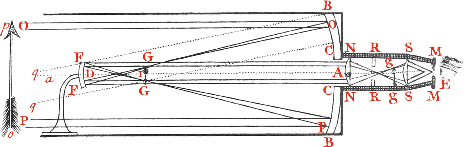
At the Bottom of a large brass Tube, Fig. 13. (expressed by a strong black Line) is fix’d a concave meta-line Speculum BB, with a round Hole CC in the middle thereof, opposite to which Hole is placed a small Speculum of the same Metal FF, concave towards the great Metal, and so fix’d to a crooked Arm, that it may be brought towards or carried from the great Speculum, keeping it’s Axis still in the same Line (viz. the common Axis of both the Speculums); and by that means parallel Rays, or Rays from the Points of a very distant Object, coming to the great Speculum in the Lines OO, PP, &c. and falling upon the great Speculum between B and C will be so united at it’s Focus, as to form there the Image GG of the Object OP, supposed to be at a vail Distance. The Rays diverging again from their respective Points of the Images, go on diverging, and fall upon the little Concave FF, whose focal Length is DI, and from it’s Surface are reflected nearly parallel to their respective Axes (not quite so, because DG is greater than DI) and with all the Axes, or principal Rays, move parallel to the convex Axis through the Hole in the great Speculum, in the Direction DA; so entering into the small Tube NMMN, which is fixed to the great Tube behind the Speculum, fall upon the plano-convex Eye-Lens NN, and passing through it form a second Image at gg, whose Bigness is limited by the Hole of a perforated opake Circle placed at RR. That second or erect Image of the first inverted Image of an erect Object, is seen large by the Eye at E, which sees it through the small Hole in the Plate MM, and the last Eye-Glass SS, which is a Meniscus. For the Eye will see it under the Angle SES, made by the Axes of those Pencils of Rays which came from the Extremities of the visible Object; and the Rays belonging to each Pencil will be parallel to their respective Axes, and the spurious Rays will be all cut off by the Plate MM, which makes the Vision distinct. This Telescope is not only good for common Eyes, but the Rays that enter the Eye will be made to converge a little for old Eyes, or to diverge a little for short-sighted Eyes, by means of a Screw fixed to the Arm of the little Concave to remove, or to bring it forwards upon Occasion.
Of Dr James Gregory’s Reflecting Telescope, as improved by Mr. Hadley.
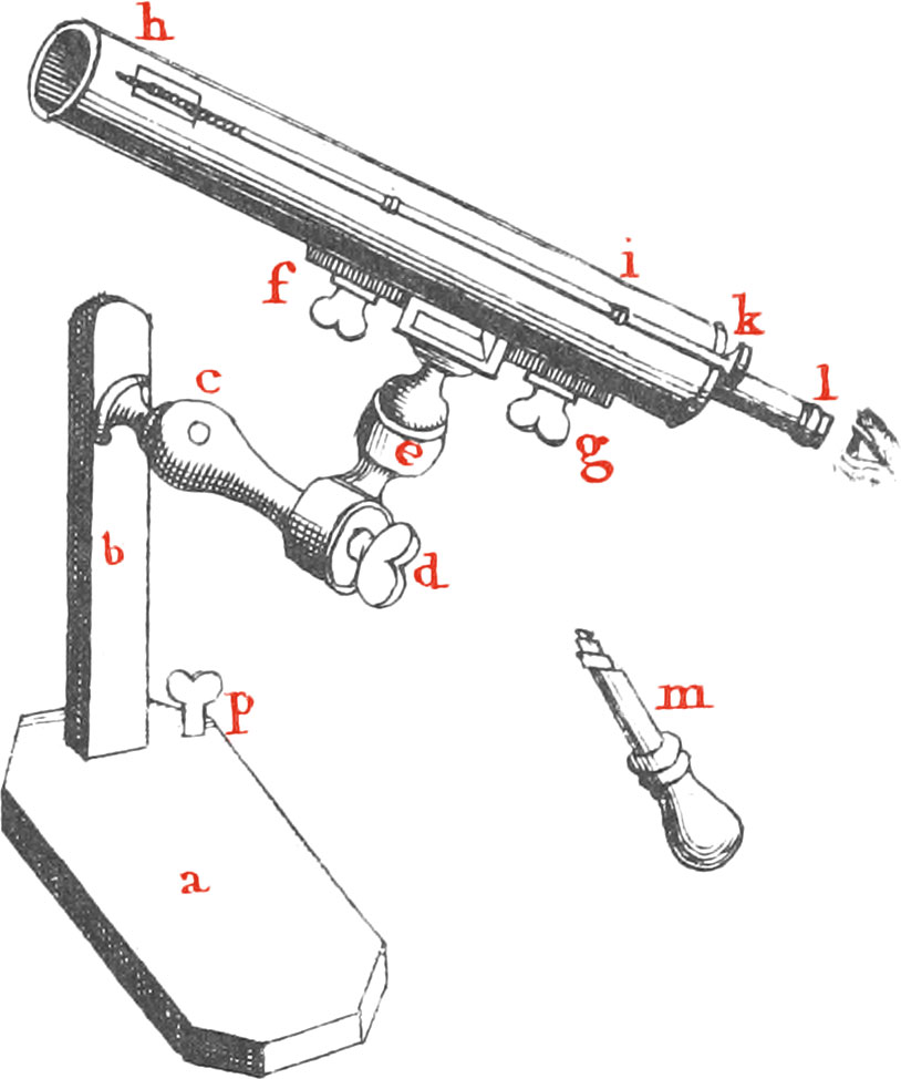
The Figure of this Telescope, upon a Support, is seen at Fig. 14. This Support is contrived thus, the Base of the Pedestal ab is a thick Board resting upon four brass Feet underneath it, one of which being a Pin p, that screws through the Board, will make it steady upon any uneven Plane, b is a small upright Pillar about a Foot long, fixed in the Board a, and cd is a brass Arm that screws into it. de is a short brass Piece, that turns round upon the End of the Arm cd, and is tightened and stayed by the Screw d. c is a hollow Socket, having a round brass Ball in it, moveable any way, and tightened and stayed by a Screw or two; the Neck of this Ball is fixed to the middle of a long brass Piece fg, which is fixed along the Side of the Tube hi, by the Screws fg, and may be taken off at pleasure. Thus the Tube is supported, and made capable of being gradually moved, and stayed in any Position. The larger concave Metal having a Hole in the middle of it, is lodged in the Bottom of the larger Tube hik, and the smaller concave Metal is held in the Axis of the Tube, near the Mouth of it, by a small brass Arm coming through a Slit in the Tube at h. The long iron Wire hik on the outside of the Tube skrews through a Hole in the Arm at h, and is confined from moving Length-ways, by two Shoulders on each side of a small Hole in a fixed Plate at i; and being turned round itself by the Knob at k, it draws the Arm and little Concave backward or forward, in order to procure distinct Vision of Objects, at various Distances, and for Eyes of different Sorts; while the Observer is looking in at the End l of a short slender Tube that is skrewed into the End of the larger, and carries the Eye-Glasses. When this Telescope is used at home, the Pedestal ab may be placed upon a Table near a Window, or upon a Window board; but when it is used abroad, the Pedestal may be left at home. For having tapped a Hole in the Side of a Tree, or any piece of Wood, with the Hand-Augre m, the wooden Screw at the End of the Arm cd, may be presently screwed into it; the Augre m being put through the Hole c, to give Power to the Hand in turning the Screw.
This reflecting Telescope made about 16 Inches long, is equivalent to a common dioptrick Telescope of above 15 or 16 Feet long; that is, magnifies as much, and is said to shew Objects as distinctly too; but of this last I am not so certain. And the Proportion of the magnifying Power of any one of them, will be as the Square of the focal Distance of the larger Concave is to the Rectangle under the focal Distance of the lesser Concave and the Eye-Glasses.
In Dr Desagulier’s appendix to the Second Edition of Dr David Gregory’s Elements of Catopricks and Dioptricks, there is not only a more particular Description of the several Parts of this Reflecting Telescope, for the sake of those who have a Mind to try at making it, but also two Tables for their Construction of other Dimensions, which the Doctor received from Mr Hadley, which being curious and useful, and the Book scarce, I shall here subjoin,
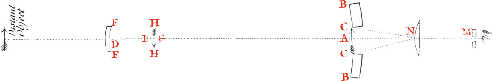
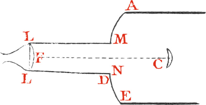
The following Dimensions in Fig. 15. are each a fourth Part of a Telescope of 12 Inches focal Length. BB is a large concave Speculum, and AG is it’s focal Length. FF is a smaller concave Speculum, it’s focal Length is ID. The Breadth FF is about \(\frac{1}{50}\) of an Inch wider than the Hole CC in the larger Speculum. N, the first Eye-Glass, is Plano-Convex. S, the second Eye-Glass, is Plano-Convex, or rather a Meniscus. M is a Plate with a small Mole in it to exclude all foreign Light, \(\frac{1}{18}\) of an Inch. RR is the limiting Circle or Diaphragm, as it is sometimes called. The Arrows are the successive Images of any Object.
Table I.
If AG be 3 Inches, or 12 Inches, of 18 Inches, or 27 Inches; and the Charge or Power of magnifying is 12\(\frac{2}{3}\) or 13; or 36, 49, 66, all correspondently taken. Then will BB be 0.7, or 2, or 2.7, or 3.7. ID, 0.82, or 2.32, or 3.22, or 4.22. FF, 0.315, or 0.56, or 0.7, or 0.88. CC, 0.295, or 0.54, or 0.68, or 0.86. The focal Distance of N, 1.48, or 3.27, or 3.97, or 4.91. The focal Length of S, 0.7, or 1.3, or 1.54, or 1.85. AD, 3.96, or 14.66, or 21.69, or 31.9. AN, 0.5, or 0.7, or 0.75, or 0.8. NS, 1.4, or 2.6, or 3.08, or 3.7. SM, 0.45, or 0.76, or 0.88, or 1.0. RR, 0.2, or 0.37, or 0.44, or 0.53.
Note, These Expressions of Inches and Decimal Parts are for the Day, where Objects are to be magnified but a little, in proportion to what the heavenly Bodies may be at Night; for which the following Table gives the Proportions.
Table II.
If AG be either 12 Inches, or 18 Inches, or 27 Inches; and the Charge be 70, or 95, or 128 Inches. Then must BD be 2, or 2.7, or 3.75. ID, 1.74, or 2.36, or 3.22. FF, 0.4, or 0.47, or 0.56. CC, 0.38, or 0.45, or 0.54. N, 2.29, or 2.79, or 3.47. The Focus of S, 0.87, or 1.03, or 1.25. AD, 13.95, or 20.64, or 30.56. AN, 0.7, or 0.75, or 0.8. NS, 1.74, or 2.06, or 2.5. SM, 0.47, or 0.56, or 0.7. RR, 0.25, or 0.29, or 0.36.
Note, The Breadth in the Hole of the Plate M must be \(\frac{1}{35}\) of an Inch. And the varying the Length of AN, the Distance of the first Eye-Glass behind the fore Surface of the Speculum BB, alters the other Proportions but a little; so that if the Thickness of the Speculum, or other Circumstances require it, there is no need to keep exactly to the Numbers here set down for it.
The Proportions of the several Parts of Gregory’s Reflecting Telescope as computed by Mr Hadley, Algebraically expressed; with numerical Examples, when the focal Length is either 40 Inches, 60 Inches, or 90 Inches.
Let (Fig. 16.) AD represent the common Axis of the Telescope, and two concave Speculums BB, FF; suppose AG the focal Length of the Speculum BB, whose proper Aperture BB, and Charge, are likewise known. Let CC be the Breadth of the Perforation. FF the Breadth of the smaller Speculum, equal to, or a little greater than CC. I it’s Focus. N the Eye-Glass. NA it’s focal Length, and M a Plate with a small Hole to exclude all foreign Light; and let it be required to take in at one View so much of the Object as may appear through the Telescope, under a given Angle, viz. CNC. To do this with the Loss of the fewest Rays of Light near the Axis; the Proportions should be as follow.
Call AG, a; 3BB, b, the Power or Charge m; the Ratio of twice the Semi-tangent of the apparent Angle of Comprehension required CNC to the Radius, that is, \(\frac{\class{fig-label}{\mathrm{CC}}}{\class{fig-label}{\mathrm{AN}}}\) = n. Then HH, the Breadth of the Image of so much of the Object as is seen at once, will be = \(\frac{n}{m}a\).
Note, If instead of \(\frac{n}{m}a\), you substitute c for HH, the algebraick Expressions become something more simple; the Breadth of the Perforation CC, and the great speculum = \(\frac{na+\sqrt{na}\ \times\ \sqrt{na+mb}}{m}\), or \(c+\sqrt{bc+cc}\). the focal Length of the small Concave ID \(\frac{a\ \times\ \sqrt{\sqrt{na}\ \times\ \sqrt{na\ +\sqrt{na\ +\ mb}}}}{\sqrt{na\ +\ mb}\ +\ \sqrt{2\sqrt{na\ \times\ \overline{na\ +\ mb}}}}\), or \(\frac{a\ \times\ \sqrt{c\ +\ \sqrt{bc\ +\ cc}}}{b\ +\ c\ +\ 2\sqrt{bc\ +\ cc}}\).
The Distances of the Specula, viz. AD = \(a+\frac{a\sqrt{na}}{\sqrt{na\ +\ mb}}\), or \(a+\frac{a\ +\ a\sqrt{c}}{\sqrt{b\ +\ c}}\).
The focal Length of the Eye-Glass, and it’s Distance from A, that is AN = \(\frac{a}{m}+\frac{\sqrt{naa\ +\ mab}}{m\sqrt{n}}\), or \(\frac{c\ +\ \sqrt{bc\ +\ cc}}{n}\).
The Distance of the plate M behind the Eye-Glass NM = \(\frac{\class{fig-label}{\mathrm{DN}}\ \times\ \class{fig-label}{\mathrm{AN}}}{\class{fig-label}{\mathrm{DA}}}\).
The Breadth of the Hole in M = \(\frac{\class{fig-label}{\mathrm{NM}}\ \times\ \class{fig-label}{\mathrm{CC}}}{\class{fig-label}{\mathrm{DN}}}\).
If a double Eye-Glass be used with this Telescope to prevent the Objects being coloured near the Edges of the Area, the Image of the Object must be thrown back by the smaller Concave, so far behind the great Speculum, that there may be Room enough to place the first Eye-Glass N at a sufficient Distance before it, and then the Algebraick Expressions of the several Parts become much more complex, and so are omitted; and I have added the following numerical Proportions for the following Sizes.
For the Night.
If AG be either 40 Inches, or 60 Inches, or 90 Inches, and the answerable Powers be either 172, or 234, or 317, then will
$$ \text{the Focal length} \left\{ \begin{matrix} \class{fig-label}{\mathrm{BB}} \\\class{fig-label}{\mathrm{ID}} \\\class{fig-label}{\mathrm{FF}} \\\class{fig-label}{\mathrm{CC}} \\\class{fig-label}{\mathrm{N}} \\\class{fig-label}{\mathrm{S}} \\\class{fig-label}{\mathrm{AD}} \\\class{fig-label}{\mathrm{AN}} \\\class{fig-label}{\mathrm{NS}} \\\class{fig-label}{\mathrm{SM}} \\\class{fig-label}{\mathrm{RR}} \end{matrix} \right\} \ \text{be}\ \left\{ \begin{matrix} 4.9 \\4.28 \\0.67 \\0.66 \\4.23 \\1.52 \\44.72 \\0.9 \\3.04 \\0.8 \\0.43 \end{matrix} \right\} \ \text{or}\ \left\{ \begin{matrix} 6\frac{3}{5} \\5.88 \\0.81 \\0.80 \\5.15 \\1.82 \\66.4 \\1.1 \\3.64 \\0.93 \\0.52 \end{matrix} \right\} \ \text{or}\ \left\{ \begin{matrix} 9 \\8.01 \\0.97 \\0.96 \\6.29 \\2.2 \\98.68 \\1\frac{1}{8} \\4.4 \\1.13 \\0.63 \end{matrix} \right. $$For the Day.
If AG be 40 Inches, and the Power 86, then will
$$ \left. \begin{matrix} \class{fig-label}{\mathrm{BB}} \\\class{fig-label}{\mathrm{ID}} \\\class{fig-label}{\mathrm{FF}} \\\class{fig-label}{\mathrm{CC}} \\\class{fig-label}{\mathrm{N}} \\\class{fig-label}{\mathrm{S}} \end{matrix} \right\} \ \text{be}\ \left\{ \begin{matrix} 4.9 \\5.95 \\1.0 \\0.99 \\6.02 \\2.22 \end{matrix} \right\} \ \text{and}\ \left\{ \begin{matrix} \class{fig-label}{\mathrm{AD}} & 6.74 \\\class{fig-label}{\mathrm{AN}} & 0.9 \\\class{fig-label}{\mathrm{NS}} & 4.44 \\\class{fig-label}{\mathrm{SM}} & 1.15 \\\class{fig-label}{\mathrm{RR}} & 0.63 \end{matrix} \right. $$In the Remarks of Dr Smith’s Opticks, pag. 104, 105. are to be found two Tables of the Dimensions, and magnifying Powers of some of the Gregorean Reflecting Telescopes, calculated by the Doctor, and founded upon the following Dimensions of one of Mr Short’s best Reflecting Telescopes of this kind, viz.
| Inches | |
|---|---|
| The focal Distance of the larger Speculum | 9.6 |
| It’s Breadth or Aperture | 2.3 |
| Focal Distance of the lesser Speculum | 1.5 |
| It’s Breadth | 0.6 |
| Breadth of the Hole in the larger Speculum | 0.5 |
| Distance between the lesser Speculum and the next Eye-Glass | 14.2 |
| Distance between the two Eye-Glasses | 2.4 |
| Focal Distance of the Eye-Glass next the Metals | 3.8 |
| Focal Distance of the Eye-Glass next the Eye | 1.1 |
The first of which is as follows:
| CT | Cx | Tc | ct | CA | ca = CB | xl | Mag. Power | r |
|---|---|---|---|---|---|---|---|---|
| 5.65 | 2.987 | 1.131 | 1.106 | 0.773 | 0.155 | 1.223 | 36.69 | 8.5509 |
| 9.6 | 4.923 | 1.653 | 1.5 | 0.15 | 0.198 | 1.565 | 60 | 9.7840 |
| 15.5 | 7.948 | 2.343 | 2.148 | 1.652 | 0.250 | 1.973 | 86.46 | 11.0090 |
| 36 | 4 | 3.724 | 3.432 | 3.132 | 0.324 | 2.561 | 165.02 | 11.7408 |
| 60 | 6 | 5.391 | 5.012 | 4.605 | 0.414 | 3.271 | 242.94 | 13.2426 |
Note. In the first Table, CT at the Head of the first Column is the focal Distance of the great Speculum. Cx is the Distance of the second Image of the Object from the great Speculum. Tc is the Distance of the lesser Speculum from the Focus of the greater. ct is the focal Distance of the lesser Speculum. CA half the Breadth of the greater Speculum, which is equal to half the breadth of the Hole in the greater Speculum. xl is the focal Distance of a Single Eye-Glass, that will magnify as much as the two Eye-Glasses, suppose m, n, of the Telescope. r is the Ratio of the Distance of the Place of the second Image from the lesser Speculum Tc.
The other Tables, with two more for Mr Cassegrain’s Reflecting Telescope, I shall not insert here.
If several Telescopes of the same Kind have nearly the same Length, or the same magnifying Powers, though of different Kinds; those are the best of their Kind by which you can read the same print at the greatest Distance, when that print is equally enlightened.
The best of these Kinds of Telescopes that have been hitherto made has been by Mr Short. He has made six with glass Speculums quicksilver’d behind, which shew the Image very distinctly, as the late Mr Maclaurin says, three of 15 Inches focal Distance, and three of 9 Inches. The present Duke of Argyle had one of the 15 Inch ones, by which it is easy to read in the Philosophical Transactions at the Distance of 230 Feet; and with one of the 9 Inch ones at the Distance of 138 Feet. With another of these, at another Time, and with a smaller Print, you may read at the Distance of 125 Feet. He has also made these Telescopes with metaline Speculums, which are very good. He has made some of 2 Inches and 6 Tenths focal Distance; others of 4, 6, 9, and 15 Inches. By those of 4 Inches the Satellites of Jupiter may be seen very well, and the Philosophical Transactions may be read at 125 Feet Distance. By those of 6 Inches focal Distance you may read at 160 Feet Distance. By those of 9 Inches at 120 Feet. By those of 15 Inches focal Distance you may read the said Transactions at the Distance of 500 Feet, and by it the five Satellites of Saturn have been seen together, which Mr Cassini had sometimes seen with a 17 Foot Refracting Telescope. See more particularly Mr Maclaurin’s Letter to Dr Smith, dated at Edinburgh, Dec. 28. 1734, to be seen at Page 80. of the Remarks, at the End of Dr Smith’s, second Volume of Opticks.
The first Thought we find in print concerning a Reflecting Telescope, is that of Dr James Gregory, in his Optica Promota, published in the Year 1663; who at Page 93, 94, proposes a Cata-Dioptrical Telescope, in order to make Telescopes shorter, and more handy; and this is the Description of it by himself.
Let ADCE (Fig. 17.) be a parabolick concave Speculum most exquisitely polished, in whose Focus C is placed a small elliptick concave Speculum, having a common Focus, and common Axis with the concave parabolick Speculum, and let it be fixed in that Situation. Now the said Focus of that elliptick Speculum must be very near to it’s vertex, and the other Focus of it must be very far from the same at F, in the common Axis produced beyond the parabolick Speculum; and through the Vertex of the parabolick Speculum must be made a round Hole MN, in which Hole must be placed a Tube, having the same Axis with the Speculums, and big enough to receive the Rays of a visible Point or Object, reflected from the elliptick concave Speculum; and let it be continued to L very near to F, and at L let a Lens of crystal Convex towards the Speculums be placed, with the Convexity of a Conoid, and the Density of the Crystalline (of the Eye), whose exterior Focus must be at F, and which must be plane towards the Eye, and likewise have the same common Axis as the Speculums and the Tube. This will be the Way to make an excellent Telescope for purblind Eyes; for distant Objects seen through the Tube, will appear distinctly magnified very near in the Ratio of the Distances of the Vertexes from the common Focus, and enlightened in the same Manner as a visible Object would be, when seen under such an Angle; provided the Diameter of what produces the last Image be big enough to suffer the Uvea of the Eye to be filled with the Rays. And how that may done, we have taught in the Scholium of the 51st of this Book, says the Doctor. But it is plain, by what Dr Gregory has here said, and by the Date of his Book, viz. in 1663, that he most certainly was the first Hinter and Founder of such an Instrument, thereby giving Occasion to others to pursue and improve upon his Original, with such Alterations or Additions, as would best make the Thing succeed in actual Practice.
Sir Isaac Newton himself tells us, in the Philosophical Transactions, Numb. 80. that he had considered this Telescope of Dr Gregory’s, as above described in the Optica Proviota; and this was not ’till the Year 1668. That he resolved, before he attempted any thing in the Practice, to alter Dr Gregory’s Design, and place the Eye-Glass at the side of the Tube, rather than in the middle.
Dr Gregory never brought his Telescope to any Degree of Perfection, but owning his Want of Skill in Mechanicks, only proposes it for others to execute; he had, indeed, an Object-Speculum of Metal ground to a Segment of a Sphere, and a little Concave, as well as a little Convex-Speculum, ground by Rives and Cox, two Optick Glass-Grinders of London, famous in those Days. But because the Object-Metal was not well polished, he only made some imperfect Trials, not so much as even fitting the Speculums and Eye-Glass into a Tube; and being discouraged, as much because he could not have the Object-Metal ground into a parabolick Concave, as because that which he tried was not well polished, he gave over the Thoughts of bringing such Telescopes into Use. See his Letter to Mr Collins, written from St Andrews, Sept. 23, 1672, to be found in Dr Desaguliers’s Appendix to Dr David Gregory’s Opticks, at Numb. 4.
Of late Years several Persons have endeavoured to make large Telescopes of this Kind, but I never heard they ever succeeded; and I must confess, that these Instruments, though they have the Advantage of magnifying, and being more manageable, yet do not shew the Objects so distinctly and bright (which are the two chief Things for which all Telescopes are Used, and valuable), as refracting Telescopes do, which are longer; besides the Trouble of making these Instruments, hazard of spoiling them, and their Expence, are Confederations of some Weight; nor can they be used, in some astronomical Observations, where a Micrometer is necessary, because a Micrometer cannot easily be applied to one of them; tho’, indeed, there is a Contrivance to do it in the Philosophical Transactions. Numb. 475.