Introduction
Mathematics is the science which treats of quantity and of the various forms and combinations of magnitudes.
The idea of magnitude applies to everything which either actually or abstractly admits of increase or diminution. Mathematics is divided into Pure and Applied. The former derives all its ideas and conclusions directly through the understanding, without requiring the least assistance from the experience and knowledge obtained through the senses, while the latter applies the deductions of the former to the various objects of experience and of the external world. Pure Mathematics distinguishes two kinds of magnitudes,—continuous, and interrupted or discrete. A magnitude is said to be continuous when its parts adhere closely together, so that the ending of one part coincides exactly with the beginning of the next; to this species belong the magnitudes of extent or space, e. g. a surface. A magnitude is interrupted or discrete when its parts are separated one from another, as the individual stones in a pile. Pure Mathematics is therefore divided into two principal sections, Geometry and Arithmetic (in its wider sense). Arithmetic, which includes Arithmetic proper, Algebra, and the analysis of finite and infinite quantities, offers from its very nature hardly any material for pictorial representations: we must therefore confine ourselves to geometry alone
Geometry (earth measuring) derives its name from a single application of the science, which will be treated of hereafter; and, as before remarked, has reference to continuously extended magnitudes, or magnitudes of space. As there are three different directions or dimensions of extension, so are there also three different kinds of magnitude or space,—lines, surfaces, and, solids; of which lines extend only in one direction (length), surfaces in two directions (length and breadth), and solids in three (length, breadth, and height or thickness). Lines are bounded by points, surfaces by lines, and solids by surfaces. Lines are divided into straight and curved; in like manner, surfaces into plane and curved. Geometry itself, however, is not divided according to the three kinds of magnitudes, but only into two principal sections,—Planimetry (Plane Geometry), and Stereometry (Geometry of Solids). The former treats of such magnitudes of space or combinations of magnitudes as are found in a single plane, or in which only two dimensions occur (length and breadth); the latter, of those in which all these three are found (length, breadth, and height or thickness), and hence it refers to solids. Geometry is again divided into the lower and higher, of which the former treats of rectilineal figures and the circle, of bodies bounded by planes, and finally of the cylinder, cone, and sphere; the latter of curved lines, of surfaces inclosed by them, and of the solids and curved surfaces which they generate.
![]() Planimetry, or Plane Geometry
Planimetry, or Plane Geometry
 Planimetry, or Plane Geometry
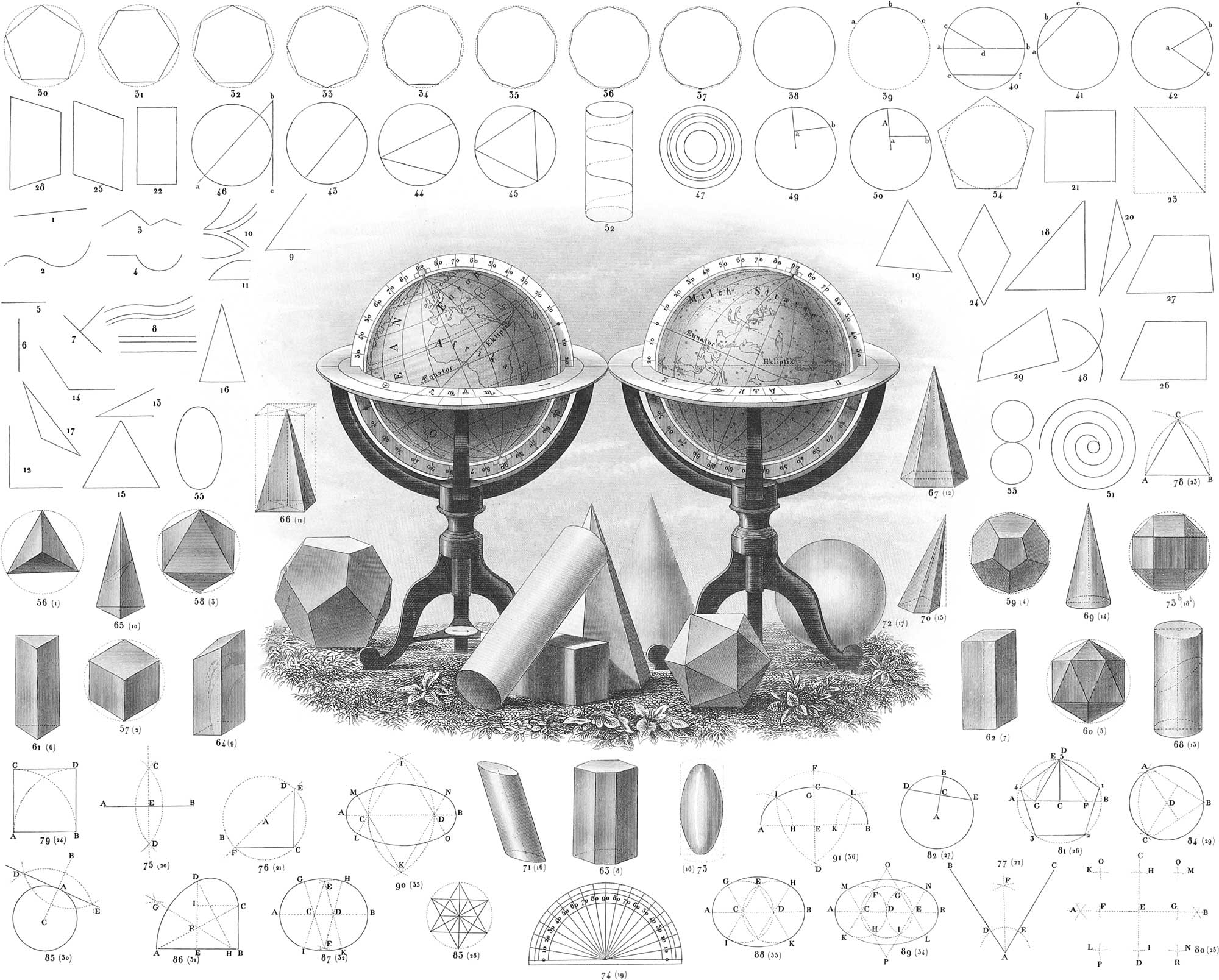
General Ideas
Lines, as already mentioned, are divided into straight (pl. 1, fig. 1) and curved (fig. 2). A broken line (fig. 3) cannot be said to be a particular species of line, but only a combination of several straight lines. A mixed line (fig. 4) is the union of straight and curved. The idea of horizontal and vertical lines (figs. 5, 6) is essentially foreign to pure Geometry. In applied or practical Geometry we call a line horizontal, when it runs in the same direction with the plane of the horizon, or the surface of still water, sometimes termed level; and vertical or perpendicular, when it corresponds to the direction of the plumb-line, or that of a string to which hangs a freely suspended weight; every other straight line is called slanting or oblique (fig. 7). Two straight lines in the same plane are said to be parallel (fig. 8) when they never meet however far they may be produced, or when they are everywhere equally distant from each other. Curved lines also, if they possess the latter property, are sometimes called parallel, although this extension of the idea is hardly allowable.
Two straight lines, when they meet in a point (fig. 9), form an angle with each other: this is the name which is given to their inclination or separation. The lines are called the sides, and the point where they meet the vertex. Any angle, even if it has both sides curved (fig. 10), or one side curved and the other straight (fig. 11), may still be reduced to a rectilineal angle. In elementary Geometry, all angles are rectilineal. If one of the sides of an angle is extended beyond the vertex, a second angle is formed, which is called the adjacent angle of the first. If the two adjacent angles are equal (fig. 7), each is called a right angle (also fig. 12). All right angles are equal; and on that account they are used as a standard by which to measure other angles. Every angle smaller than a right angle is called acute (fig. 13), and every angle that is larger is called obtuse (fig. 14). Two or more angles that have a common vertex, and lie on the same side of a straight line in such a manner that this line constitutes one side of the first angle and one of the last, are altogether equal to two right angles. The angles about a point are together equal to four right angles.
A flat space bounded by lines is called a figure. A figure is called rectilineal if it is bounded by straight lines; if by curved lines, curvilineal; and it is a mixed figure when it is inclosed by both straight and curved lines. Plane Geometry deals only with plane figures (figures that lie in a plane surface). If a rectilineal figure is bounded by three lines, it is called a triangle; if by four, a quadrilateral; if by more than four, a polygon.
Triangles are divided, first, according to their sides, into equilateral (pl. 1, fig. 15), in which all the sides are equal; isosceles (fig. 16), which have only two sides equal; and scalene (fig. 17), in which all the sides are unequal. Secondly, they are divided with reference to their angles, into right angled triangles (fig. 18), when they have one angle right and two acute; obtuse angled triangles (fig. 20), when they have one angle obtuse and two acute; and acute angled triangles (fig. 19), when all the angles are acute. That side of a right angled triangle which is opposite to the right angle is called the hypothenuse, the two others are called the legs.
Among quadrangular figures, the parallelograms form a remarkable class. They are quadrilaterals in which the two opposite sides are equal and parallel. Every parallelogram is divided by a diagonal—a straight line joining the vertices of two opposite angles—into two equal triangles (fig. 23). There are four different kinds of parallelograms: the square (fig. 21), in which all the sides are equal, and all the angles right angles; the rectangle (fig. 22), which has also its angles right angles, and only its parallel sides equal; the rhombus or lozenge (fig. 24), in which all the sides are equal, but only its opposite angles equal; and the rhomboid (fig. 25), which has only its opposite sides and angles equal. A quadrilateral in which only two sides are parallel is called a trapezoid (fig. 27). It is called a right angled trapezoid when it has two right angles (fig. 26), and equilateral when the two sides that are not parallel are equal (fig. 28). A trapezoid may have three sides equal, but the parallel sides must always be unequal. A quadrilateral in which none of the sides are parallel is called a trapezium (fig. 29).
A polygon is called regular when all its sides and angles are equal, and irregular when this is not the case. Figs. 30–37 represent regular polygons, viz. fig. 30, a 5-sided figure, or pentagon; fig. 31, a 6-sided, or hexagon; fig. 32, a 7-sided figure, or heptagon; fig. 33, an 8-sided, or octagon; fig. 34, a 9-sided figure, or nonagon; fig. 35, a 10-sided, or decagon; fig. 36, one of 11 sides, or undecagon; fig. 37, one of 12, or dodecagon; all of which are accompanied by circles, either circumscribed or inscribed.
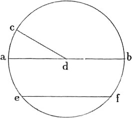
The only curved line which occurs in elementary geometry, is the circular. The extremities of this line meet, and every point in it is equally distant from a point in the space inclosed, called the centre. The surface inclosed by the circular line is called the circle (fig. 38). In its relation to this, the circular line is called the circumference or periphery. A portion of the circular line is called an arc, e. g. abc (fig. 39). The size of an arc with reference to the whole circumference is measured by degrees. Every circle is divided into 360 equal parts, which are called degrees; each degree contains 60 minutes, and each minute 60 seconds. A straight line, drawn from the centre of a circle to its circumference, is called a semi-diameter or radius, e. g. cd (fig. 40); a straight line uniting two points of the circumference, a chord, e. g. ef (fig. 40, also fig. 43); and a diameter when, passing through the centre, it unites two opposite points of the circumference, as ab (pl. 1, fig. 40). Every chord cuts from a circle a segment, as bac (fig. 41). The part of a circle included between two radii and an arc is called a sector (fig. 42). The angle formed by two radii is called a centre angle, as bac (fig. 42). An angle formed by two chords meeting in the line of the circumference, is called an inscribed angle (fig. 44). When a straight line, produced at pleasure, touches a circumference only at one point, it is called a tangent, e. g. bc (fig. 46); any such straight line, however, which either immediately or when produced cuts the circumference in two points, is called a secant, ab (fig. 46). A rectilineal figure is said to be inscribed in a circle when all its sides are chords (fig. 45); it is said to be circumscribed about a circle when all its sides are tangents (fig. 54). Two or more circles are said to be concentric when they have a common centre (fig. 47); circles of different centres are excentric. Two excentric circles touch one another when their circumferences have only one point in common: this point may be either on the exterior (fig. 53) or on the interior of the circumference. In the first case the sum, in the second the difference of their radii, will be the distance between their centres; in both cases the centres and the point of tangency will be in the same straight line. Two excentric circles cut each other (fig. 48) when their circumferences have two points in common. Each point of intersection forms a triangle with the two centres.
Of the Position of Straight Lines in the Same Plane
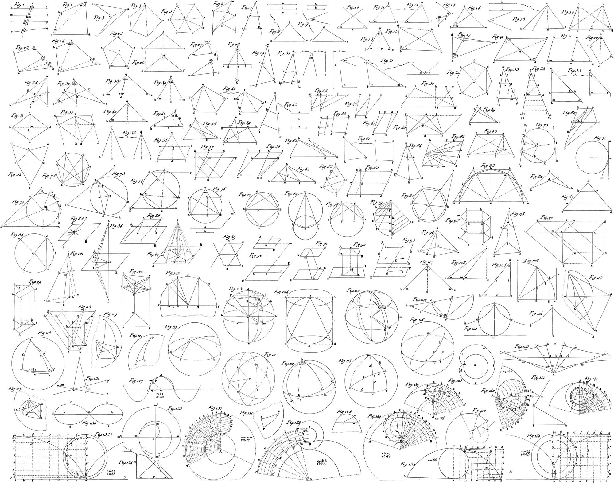
Only one straight line can be drawn between two given points, so that the position and direction of a line is completely determined by these points. On the other hand, innumerable curved lines are possible between two points. A straight line is the shortest distance between two given points. Hence it follows that in a triangle each of the sides is less than the sum, but greater than the difference of the two others. If two triangles have the same base, so that the one lies entirely within the other, the outer has a greater perimeter than the inner (pl. 3, fig. 82). Two straight lines on one plane may intersect each other, either directly or when produced; they can, however, have but one point in common, or they may never meet even when produced. In the first case, they converge and form an angle; in the second, they are parallel. If two lines, whether parallel or not, as kl, mn, or op, qr (fig. 1), are intersected by a third straight line, st, then there will be eight angles formed,—four internal and four external: of these, the two internal or two external angles which lie on opposite sides of the secant line, and are not adjacent to each other, are called alternate angles, as a and h, c and f, i and u, m and n. Then again, two angles, one internal and the other external, lying on the same side of the secant without being adjoining, are called opposite angles; e. g. a and i, c and g, k and o, m and n. When parallel lines are intersected by a third straight line, each two of the alternate angles, as well as of the opposite, are equal to each other. In every triangle, the sum of all the angles is equal to two right angles. The angles of a quadrilateral are together equal to four right angles, as will become evident if we divide the quadrilateral by a diagonal into two triangles (pl. 1, fig. 23). The sum of the angles in a pentagon is equal to six right angles, since two diagonals divide it into three triangles (pl. 3, fig. 4). And in general, the sum of the angles of a rectilineal figure is always equal to twice as many right angles, less 4, as the figure has sides. This proposition will become clearer if we draw, from a given point within the figure, lines to all its corners (fig. 5), and remember that the sum of all angles that have their vertex in one common point, is equal to four right angles. This proposition also holds good if the figure have a re-entrant angle (fig. 6); but in order to prove it in that case, it will be better to divide the figure by diagonals that must not intersect one another, into triangles, of which there will always be two less than the figure has sides.
Of the Equality of Figures
Two figures are said to be equal when they can be so applied to each other as to coincide throughout. The sides and angles of a figure are in such intimate and dependent relation, that from the equality of some of them we may infer the equality of the rest. For example, if of two triangles we know that three parts are mutually equal—either the three sides, or two sides and the included angle, or two sides and the angle which is opposite the greater of the two, or two angles and the included side—then may we conclude from this that the rest of the parts are also equal each to each, and that the triangles themselves are equal (pl. 3, figs. 11, 12). But of the three parts ascertained, one must always be a side, since two triangles of unequal sides may have equal angles, as in fig. 7. If, in this triangle ade, we add to de the parallel bc, then it is plain that the triangles abc and ade have their angles equal, since q = q, m = n, o = p; but the triangles themselves are by no means equal, since the one is only a part of the other. From these cases of equality it follows also what parts are necessary to construct a triangle. This is most easily done by having the three sides, a, b, c, given (fig. 8); but we may also employ two sides, a, b, and the included angle m (fig. 9), as well as two angles, m, n, and the included side a (fig. 10); or finally, two sides, a, b, and the angle m (fig. 18) lying opposite to one of them. It is to be observed, however, that when this angle lies opposite to the smaller of the two sides, two different triangles may be constructed, both of which will answer the conditions of the proposition, so that in this case the triangle is not completely defined. By means of the equality of triangles the following, among other properties, may also be proved: 1. In an isosceles triangle, the angles opposite the equal sides are also equal (fig. 13), for let ab = ac, and from a draw a line which bisects bc, then there will be two equal triangles in which ∠ m = ∠ n, from which it follows that o = p, and q = r, which shows that the line is perpendicular to bc, and bisects the angle at a. In an equilateral triangle, all the three angles are equal. 2. The greater angle of a triangle lies opposite to the greater side, and vice versâ. If, in the triangle abc, (fig. 14), ab is greater than ac, then is also ∠ acb greater than ∠ abc, &c. 3. If two triangles have two sides of the one equal to two sides of the other, each to each, and the included angle unequal, the third sides will be unequal, and the greater side will belong to the greater triangle, which has the greater included angle; or if an angle of a triangle is increased, while its including sides remain the same, then will the side opposite the angle be also increased (figs. 15–17).
A quadrilateral is a parallelogram, when it can be proved,—1, that two of its opposite sides are equal and parallel; or 2, that all the opposite sides are equal; or 3, that all the opposite sides are parallel.
The opposite angles of a parallelogram are also equal: two adjacent angles form together two right angles (fig. 22).
Hence all the angles in a parallelogram are either right angles or two are acute and two obtuse (rhombus and rhomboid). The two diagonals of a parallelogram mutually bisect each other (fig. 19).
To construct a parallelogram it is generally necessary to have two sides and an angle given. For a rectangle, however, two sides are sufficient; for a rhombus, one side and an angle; and for a square, one side. A trapezoid can be constructed by means of its four sides (pl. 3, fig. 21), by constructing first a triangle out of the two sides ad, ae, which are not parallel, and the difference of the parallel sides de, then producing de to c, so that ce may become equal to the lesser parallel, and with aec, the parallelogram abce will be completed. A trapezium may be constructed,—1, with four sides and an angle; 2, with three sides and the two included angles; 3, with three sides and the angles lying about the unknown side; 4, with two adjacent or two opposite sides and the three angles (figs. 23, 24).
Every regular polygon has a central point which is at an equal distance from all its sides and from all its angles. This point is found by bisecting two angles, for the bisecting lines always meet in that common centre (fig. 25).
The preceding propositions concerning the equality of triangles, enable us to solve and prove the solution of a number of problems of easier construction. Among these are: 1. to construct a triangle equal to a given triangle (fig. 26). 2. To describe a given angle m, on a given straight line ab, at a given point a (fig. 27). 3. Through a given point, to draw a line parallel to a given line. 4. To bisect a given angle (pl. 2, fig. 77). 5. To bisect a given line (fig. 75). 6. To draw a perpendicular to a line at a given point. 7. From a given point out of a line, to let fall a perpendicular on that line (pl. 3, fig. 28, and pl. 2, fig. 75). 8. To draw a perpendicular at the extremity of a given line (pl. 3, fig. 29, and pl. 2, fig. 76). 9. To draw a given line between the sides of a given angle bac, so that it may form a given angle m with one of the two sides (pl. 3, fig. 30). 10. To construct a triangle with a given line a, and two given angles m and n [the sum of which must be less than two right angles], (fig. 31). 11. To construct an equilateral triangle upon a given base (pl. 2, fig. 78). 12. To construct a square upon a given base ab (pl. 2, figs. 79, 80). In order to obtain a regular octagon from a square, we must proceed as follows:—Draw (pl. 3, fig. 32) the two diagonals of the quadrilateral intersecting at e; bisect the angle ced; make the bisecting line ef = ce or de, and draw cf and df; finally, describe upon the remaining three sides of the quadrilateral, equilateral triangles, which are equal to the triangle cdf.
Of the Similarity of Figures
Two figures are called similar when they agree in their form, or more definitely, when the angles of the one are equal to the angles of the other each to each in the same order, and the sides of the one are in the same proportion as those of the other. We arrive at the latter definition as respects triangles, by examining two lines not parallel to each other, which are intersected by several parallel lines. If we divide one of the two lines aq, ar (pl. 3, fig. 33), into the equal parts, ab = bc = cd = de, commencing at the point of intersection, and then draw from the points of division, b, c, d, e, parallel lines, then the divisions of the other lines thus formed will also be equal to each other. If, again, we take in one of the two lines aq, ar (fig. 34), two or more unequal parts, beginning at the point of intersection a, and then draw parallel lines from the points of division b, c, then will the resulting sections, ad, de, of the other line, be in the same proportion to one another as the sections, ab, bc. In this case the triangles abd, ace, are similar; we readily perceive that their angles are equal, and that two sides of the one triangle are always in the same proportion as the corresponding and similarly placed sides of the other. To be certain that two given triangles, abc, def (fig. 35), are similar, it is only necessary to know,—1, that two angles, or 2, that one angle and the ratios of the including sides, or 3, that the ratios of two of the sides and the angles opposite to the greater of them, or 4, that two ratios of sides, are equal.
The following propositions, among many others, may be proved by means of the similarity of triangles. If in a triangle abc (pl. 3, fig. 36), lines be drawn from two angles, a, b, to the middle of the opposite sides, each of these lines cuts the other into two parts, of which the one lying towards the bisected side is half of the other. From this it readily follows that all the three lines drawn from the angles of a triangle to the middle of the opposite sides, pass through one and the same point. If we bisect the angle a of the triangle abc (pl. 3, fig. 37), it may be readily shown that the segments into which the opposite side be is divided by the bisecting line, are in the same proportion as the two other undivided sides, thus, bd : ed :: ab : ac. Hence we deduce the proposition, that lines bisecting the three angles of a triangle cut each other in one and the same point, which is of importance, as being the centre of the circle inscribed in the triangle. To cut off from a given triangle a smaller one similar to it, we may either, 1, draw a line parallel to one side of the triangle, or 2, from one angle of the triangle, not the least, cut off by a line another angle equal to a smaller one of the same triangle. E. g., if in fig. 38 the angle n = m, then will the triangle acd be similar to abc. And if the second triangle, abo thus formed, is also to be similar to the original triangle, then must q = o, also n + q or bac = m + o, which is only possible when bac is a right angle. In this case the bisecting line ad is perpendicular to bc. If, therefore, in a right angled triangle, we let fall a perpendicular from the vertex of the right angle upon the hypothenuse, the perpendicular thus let fall will divide the triangle into two smaller ones, similar to each other and to the original triangle fig. 39–41). From this may be easily deduced, 1, that the perpendicular let fall from the vertex of the right angle, is a mean proportional between two segments of the hypothenuse; 2, that either side about the right angle is a mean proportional between the whole hypothenuse and adjacent segments. From the latter proposition follows another: that when the sides of a right angled triangle are expressed in numbers, the square of the hypothenuse will be equal to the sum of the squares of the other two sides.
With respect to the similarity of such rectilineal figures as have more than three sides, we will confine ourselves here to the following proposition: two figures are similar, when they can be divided by similarly situated diagonals into triangles which are similar each to each (pl. 3, fig. 42).
Similarity of figures may also be applied to the solution of numerous problems of construction, of which we will here mention only one;—to find a fourth proportional to the three given lines, a, b, c (fig. 43). This is a problem of the same importance in Geometry as the Rule of Three is in Arithmetic.
Of the Equivalence of Areas in Figures
Figures are said to be equivalent when they occupy equal areas. In equality we combine similarity with equivalence. We must here premise that in triangles and parallelograms, some one side is assumed as the ground line or basis upon which the figure is supposed to rest, and that then the height or altitude is the perpendicular distance from this basis to the opposite side or angle.
Two parallelograms are equivalent, when their bases and altitudes are equal (pl. 3, fig. 45–47). Here we may always consider them as erected upon the same base, and the opposite sides will then be in one and the same parallel; in which case, apart from the condition of equality or complete coincidence, three conditions, as represented in figs. 45, 46, 47, are possible. A triangle is always the half of a parallelogram of the same base and altitude, therefore equal to a parallelogram of the same altitude and half the base, or to one of an equal base and half the altitude; whence it follows that triangles of equal bases and altitudes are equivalent (fig. 48). If we assume in succession two different sides of the same triangle as bases, they will be inversely proportional to their corresponding altitudes, viz. ab : ac :: bc : cd (fig. 49). A trapezoid may be divided by a diagonal into two triangles, which will have the parallel sides of the trapezoid for their bases, and the perpendicular distance between these sides for their common altitude; it is, therefore, equal to a parallelogram whose base is equal to half the sum of the parallel sides, and whose altitude is equal to their perpendicular distance from each other (fig. 50). A rhombus, whose diagonals are perpendicular to each other, will be four times as large as a right angled triangle, which has for its two legs half the diagonals of the rhombus (fig. 51). The areas of two parallelograms as well as of two triangles of the same base, are to each other as their altitudes; of the same altitude, as their bases; and generally, parallelograms are to each other as the products of their bases by their altitudes. The areas of two squares are to each other as the squares of their sides. The areas of two similar triangles are to one another as the squares of their homologous or similarly situated sides (fig. 53); the same is true generally with regard to the areas of two similar figures. If on the three sides of a right angled triangle, three similar figures, triangles or any others, be constructed, the figure on the hypothenuse will be equivalent to the sum of those on the two legs (pl. 3, fig. 54). A particular case of this proposition is known as the Pythagorean: the square described upon the hypothenuse is equivalent to the sum of the squares described on the other two sides.
As the unit of measure for the determination of the superficial relations of figures, we use a square whose side is equal to the unit of length, which, therefore, according to the length of the side, is called a square foot, a square inch, &c. To ascertain how many times one square is contained in another, it is necessary to find out how many times the side of the one is contained in that of the other, and the number thus obtained multiplied by itself; hence a square foot contains not 10 or 12 square inches, but 100 or 144, according to the number of inches, 10 or 12, into which the foot is divided, &c. The area of a square may thus be found, by measuring one of its sides and then multiplying the number expressing its length by itself. Hence we are accustomed to call the product of a number by itself, or the second power, its square. The area of a parallelogram is found by multiplying the base by the altitude (expressed in the same unit of measure); that of a triangle by multiplying the base by half the height, or the height by half the base; that of a trapezoid by multiplying half the sum of the parallel sides by their perpendicular distance; that of a regular polygon by multiplying its circumference or perimeter by half the perpendicular let fall from the centre on one of the sides; that of an irregular polygon by dividing it by diagonals into triangles, whose areas must be separately ascertained and added together.
By the assistance of the preceding propositions, many problems relative to the changing and dividing of figures may be solved. A few of these problems are the following:—1. To change a triangle into a parallelogram of equal area, or the contrary (fig. 55). 2. To change the triangle abc into another of equal area, and with a given side be (fig. 56). 3. To change a parallelogram into a rhombus of a given side cf (fig. 57), or of a given angle m (fig. 58). 4. To change a given triangle abc into an equilateral triangle (fig. 59). 5. To change a quadrilateral abcd into a triangle (fig. 60). 6. To change a given figure into another of a prescribed shape, e. g. the triangle abc (fig. 61) into a quadrilateral similar to the given quadrilateral defg. 7. To divide a triangle into a certain number of equal parts by lines proceeding from one angle. 8. To cut off from a triangle a certain portion, as for instance a third, by means of a line which is to proceed from a given point, d, in one of its sides (fig. 62). 9. To cut off from a triangle, abc, a certain part, as a third, by lines proceeding from a given point, d, within the triangle (fig. 63). 10. From a triangle, abc, to cut off a certain portion, by a line parallel to one of the sides (fig. 64). 11. To divide a parallelogram into a given number of equal parts, by lines parallel to one of its sides. 12. From an acute angled parallelogram to cut off a given part by a line perpendicular to two of the sides (pl. 3, fig. 65). 13. To divide a parallelogram, abed, into a certain number of equal parts, by lines proceeding from a given point in one of the sides (fig. 66). 14. From a trapezoid, abed, to cut off a given part, for instance the half, by a line parallel to its parallel sides (fig. 67). 15. To cut off from any quadrilateral, abcd, a given part, by a line proceeding from a corner, a, or from a given point, e, in one of its sides (figs. 68, 69).
Of the Circle and its Measurement
A circular line cannot have more than two points in common with a straight line (fig. 70). A straight line intersects or touches the circle, according as it has two points in common with the circumference, or only one; in either case we must consider the line as indefinitely produced in either direction. We obtain a tangent, when we draw a perpendicular to the extremity of a radius or diameter (fig. 71). On the other hand, a radius drawn to the point of tangency of a tangent, will be perpendicular to it; whence it follows, that to any point of a circumference only one tangent can be drawn. Lines drawn from the same point, tangent to a circumference, are equal to each other, e. g. su = sv in fig. 72.
Equal angles at the centre of the same circle, or of equal circles, have equal chords and areas, and the reverse. An angle at the centre is measured by the number of degrees contained by its arc. An inscribed angle is half the angle at the centre of the same arc, and is therefore measured by the half of its arc. An angle formed by a tangent and a chord is measured by half the arc included between the tangent and the chord (fig. 73). Inscribed angles resting upon the same or upon similar arcs are equal (fig. 75). When two chords intersect each other, either within the circle, or when produced, without it, the angle thus formed is measured in the first case by half the sum, and in the second by half the difference of the two arcs included between the chords (fig. 74). Every angle inscribed in a semicircle is a right angle (fig. 77). If at any given point of a diameter a perpendicular be drawn to the circumference, it will be a mean proportional to the two segments of the diameter (fig. 78).
From the preceding propositions may be obtained the solution of the following problems: 1. To find the centre of a circle or of a circular arc (pl. 2, fig. 84). 2. To bisect a circular arc. 3. To draw a tangent to a given point in a circumference (pl. 2, fig. 85). 4. From a given point out of a circle, to draw a tangent to the circle (pl. 3, fig. 80). 5. Upon a given base, ab, to construct a triangle in which the angle opposite the base is equal to the given angle m (fig. 76). This problem is indefinite, since every point of an arc may be taken as the vertex of the triangle; but it becomes definite if the height of the triangle is also given. A particular case is exhibited in the problem: upon a given line, as hypothenuse, to construct a right angled triangle. 6. To construct a mean proportional to two given lines. 7. To divide a given triangle, abc, by lines running parallel to a given side, into a certain number of of parts, five for instance, that shall be either equal, or in a definite proportion (fig. 79).
The construction of regular polygons in and about the circle, is of importance in understanding its theory. A regular polygon is said to be inscribed in the circle, when all its sides are chords; and circumscribed about the circle, when all its sides are tangents. A regular polygon is inscribed in a circle, by dividing the circumference of the latter into as many equal parts as the polygon is to have sides, and connecting these points by chords. The difficulty here lies only in dividing the circumference into a given number of equal parts. The division into four or six parts is most easily made the former, by drawing two diameters perpendicular to each other; the latter, by using as chords, lines equal to the radius (fig. 81). To divide the circumference into ten equal parts, we draw two radii perpendicular to each other, bisect the one, and connect the point of bisection with the extremity of the other, and then cut off from this connecting line a section equal to the half of the radius; the remainder will be the length of a chord whose arc is the tenth part of the circumference, or the side of a regular inscribed decagon. Pl. 2, fig. 81, shows the construction of a regular pentagon in a circle. AB is here a diameter, CD a radius perpendicular to it; from F the middle point of BC, with a radius equal to FD, we describe an arc intersecting AC in G; draw DG; this will be the side of the regular pentagon (CG will be the side of the regular decagon). We may obtain a pentagon by connecting the alternate angles of a decagon. From the division into four equal parts, we may readily obtain that into 8, 16, 32, &c., and the division into 10, 20, 40, 80, &c. The fifteenth part of the circumference is found by subtracting the 10th part from the 6th, for \(\frac{1}{2}\) − \(\frac{1}{10}\) = \(\frac{4}{60}\) = \(\frac{1}{15}\).
A regular polygon is circumscribed about a circle, by dividing the circumference into as many equal parts as the polygon is to have sides, and then drawing tangents to all the points of division. From a polygon of any given number of sides inscribed in the circle, we may obtain a regular polygon of double the number of sides, by bisecting the arcs, whose chords form the sides of the former, and drawing chords to the half-arcs. The circumference (as well as the area) of a circle is always greater than the perimeter (or area) of an inscribed polygon, but is less than the perimeter (or area) of one circumscribed about it (pl. 3, fig. 83).
The circumference of a circle cannot be directly measured, since it is not a straight line; but if two polygons of a great number of sides be described in and around it, and their circumferences determined, that of the circle will be intermediate. In this way Archimedes determined the ratio of the diameter to the circumference as 7 : 22, and Ludolph, as 1 : 314159. The latter number is employed and indicated by π, as the ratio to a diameter of 1 (or unity). Accordingly, since circles are to each other as their diameters, the circumference of any circle may be found by multiplying its diameter by π (= 3.1415926).
Every circle may be regarded as a regular polygon of an infinite number of sides; hence, also, as a triangle whose base is equal to the circumference of the circle, and whose altitude is the radius. We consequently obtain the area of a circle by multiplying the circumference by half the radius, or according to the preceding proposition, by multiplying the second power of radius by π. A sector is equal to a triangle whose base is the length of the arc, and whose altitude is equal to the radius (pl. 3, fig. 84).
Allied to the circle are the symmetrically curved lines, the oval and the ovate: each one consisting of four elongated quadrants. In the former the quadrants are all equal; in the latter only the two lying on the same side of the short axis. The following are some constructions of ovals. In pl. 2, fig. 87, an isosceles triangle, CDE, is constructed upon the base CD, and under it another and equal arc, CDF. From C and D, with any radius, CA = DB, describe arcs intersecting the equal sides produced of each triangle in G and I, H and K: and finally, connect these points by arcs described with the radii FH = EK, from F and E as centres. Fig. 88 agrees with the preceding construction, except in that the two equal triangles employed, are equilateral. In fig. 88, the length of the oval, or of the major axis, AB, is given. Divide it at C and D, into three equal parts. From the points C and D, with radii equal to \(\frac{1}{3}\) AB, describe circles intersecting in E and F. From these points draw two diameters in each circle, GF, EI, FH, EK, and with one of these diameters as radius, from the points E and F, describe the arcs IK and GH, completing the outline. In this construction the breadth of the oval is a little more than \(\frac{3}{4}\) of the length. An oval of less breadth, with the same length, AB, may be thus obtained (fig. 89). Divide AB into four equal parts, and from the points of division, C, D, E, with a radius equal to \(\frac{1}{4}\) of AB, describe three circles, intersecting each other in F, G, H, and I. Through these points draw in the first and third circles the diameters MH, NI, FK, and GL, prolonging them until they intersect in O and P. From O and P, with radii OK = PM, describe the arcs KL and MN. In this construction the breadth of the oval is not quite \(\frac{2}{3}\) the length. In fig. 91, a half-oval of given length, AB, is constructed in the following manner. From the points A and B, in the line AB, any part, AH = BK, is taken, and with this distance as radius, arcs are described cutting each other in I and L; with the distance between I and L as radius, describe, from these points as centres, arcs cutting each other beneath AB; finally, from D as centre, complete the circle by the arc IL.
![]() Stereometry, or the Geometry of Solids
Stereometry, or the Geometry of Solids
 Stereometry, or the Geometry of Solids
Of the Position of Lines and Planes in Space
Through one or two points, as well as through one straight line, innumerable planes may pass. Only one, however, can pass through three points not in the same straight line, through two parallel or intersecting straight lines, or through a straight line and a point external to it. Two planes meeting each other without coinciding, form a straight line by their intersection. A straight line not in a plane, can have only one point in common with it. It is perpendicular to the plane when it is perpendicular to all straight lines drawn through its foot in the plane; this is likewise the case when it forms a right angle with two lines lying in the plane (pl. 3, figs. 86, 87). The angle of inclination of a line to a plane not perpendicular to it, is found by letting fall a perpendicular from any point of the line upon the plane, and connecting the extremities of the two lines by a line situated in the plane. This is the least angle which the straight line can make with lines drawn through its foot on the plane. Two straight lines perpendicular to the same plane, are parallel to each other (fig. 90). If, of two parallels, one stands perpendicular to a plane, the other must also A straight line is parallel to a plane, as well as a plane parallel to a straight line, when they will not meet if produced. If a straight line be parallel to a plane, and we pass through the line, planes cutting the first plane, the lines of intersection will be parallel to each other and to the plane (fig. 88). Two planes perpendicular to the same straight line are parallel to each other (fig. 90). Two parallel planes, intersected by a third, will have the lines of intersection parallel (fig. 91). If two straight lines in space be intersected by three parallel planes, the segments of the one will be proportional to those of the other (fig. 93). Parallels or perpendiculars between two parallel planes are equal; hence the distance between two parallel planes is measured by a perpendicular let fall from one upon the other. Two angles which have three sides parallel are equal; if they lie in different planes, these latter are parallel (fig. 92). The inclination or separation of two planes not parallel, is measured by the angle formed by lines in each plane, drawn perpendicular to a point in the line of intersection of the planes. Planes, like lines, may form adjacent and opposite or vertical angles, which, with respect to their magnitudes, have the same properties as those of lines (fig. 89). Two planes are perpendicular when their angle is a right angle. If a plane be perpendicular to two intersecting planes, it will also be perpendicular to their line of intersection. If a straight line be perpendicular to a plane, every plane passing through the former will be perpendicular to the latter. When three or more planes meet in one point, they form a corner or solid angle (pl. 3, fig. 94). The edges or lines of intersection of planes meeting in this manner, form as many plane angles as there are planes. If the solid angle be formed by three planes, then is the sum of any two of the plane angles greater than the third. In any case, however, the sum of any number of plane angles, forming a solid angle, is less than four right angles.
Of Angular Solids
A solid may be inclosed either by plane surfaces alone, in which case it is called a polyhedron, or by curved surfaces alone, or by both plane and curved at the same time. Bodies of the first and third kind have a base, that is, a plane surface upon which the solid is supposed to rest. If such a body should have another plane bounding surface parallel to this base (in which case this plane may be considered another base), or a vertex opposite to the base, the distance between the two surfaces, or between the vertex and the base (in both cases measured by a perpendicular let fall), is called the altitude of the solid. The planes bounding a polyhedron are called its faces; their intersections, its edges. No polyhedron can have less than four faces, four solid angles, or six edges. Furthermore, no polyhedron can be inclosed by figures of six or more sides, or have equal solid angles formed by six or more plane angles.
Two solids are said to be equivalent when the spaces inclosed between their bounding surfaces are equivalent; they are equal when they agree exactly in shape and size, so that the one may be taken for the other.
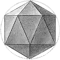
A polyhedron is called regular when it is inclosed by perfectly regular and equal figures, and has all its angles equal. There are only five regular solids; 1, tetrahedrons, bounded by four triangles (pl. 2, fig. 56); 2, octohedrons, by eight (fig. 58); 3, icosahedrons, by twenty (fig. 60); 4, hexahedrons, bounded by six squares (fig. 57); 5, dodecahedrons, by twelve pentagons (fig. 59). The expansion of some of these solids, or the representation of their surfaces as spread out in a plane, may be found in pl. 4, where fig. 49 is the expansion of the tetrahedron, fig. 50 that of the hexahedron, fig. 51 of the dodecahedron. A solid, bounded by regular figures of two kinds, and which has, at the same time, all the solid angles equal, is called an Archimedean solid. If we limit ourselves to polyhedrons having triangles and squares for faces, such a solid may be contained, 1, by two triangles and three squares (a special case of the three-sided prism); 2, by eight triangles and six squares; 3, by eight triangles and eighteen squares (pl. 2, fig. 73b); and, 4, by thirty-two triangles and six squares.
The most important angular solids are the prisms and pyramids. A prism is a solid bounded by two equal and parallel rectilineal figures (forming the bases) and as many parallelograms as each base has sides. It is called three, four, five-sided, as the bases are triangles, quadrilaterals, pentagons, &c. (pl. 2, figs. 61, 62, 63). The prism is called a right prism if the lateral faces are perpendicular to the bases, otherwise it is oblique. A four-sided prism whose bases are parallelograms, is called a parallelopipedon; when all the faces are squares, it is a cube or hexahedron. If a prism be intersected by a plane parallel to the base, the section formed will be equal to the base (pl. 3, fig. 96). The sections of two planes parallel to each other, but not to the base, are equal. Plate 2, fig. 64, represents a parallelopipedon intersected by a plane, not parallel to the base. Prisms of equivalent bases and equal altitudes are equal to each other (pl. 3, figs. 97–99). Prisms of equal bases, but of unequal altitudes, are to each other as their altitudes; those of equal altitudes, as their bases; those of unequal bases and altitudes, as the product of the two. A cube whose edge is the unit of length, serves as the unit of measure for determining the volume of a solid; it is called cubic foot, cubic inch, &c., as the edge is a foot, inch, &c. The volume of a cube is obtained by raising the number expressing the length of its edge, to the third power; that of any prism in general by multiplying the area of the base by the altitude, the same unit of measure being used in both.
A pyramid is a solid, bounded by any rectilineal figure as base, and as many triangular planes meeting at the vertex as the base has sides. It is called three, four, or five sided, &c., as the base has three, four, five, or more sides (pl. 2, figs. 65, 66, 67, 70). If a plane be passed through a pyramid, parallel to the base, the section thus formed will be similar to the base, and will bear to it the same proportion as the square of the perpendicular let fall from the vertex on the section, to the square of the altitude of the pyramid (pl. 3, fig. 95). A three-sided prism may be divided into three equivalent pyramids, of which two have the same base and altitude as the prism. Hence it follows that every pyramid is \(\frac{1}{3}\) the prism of equivalent base and altitude. Consequently, the solid content of a pyramid is obtained by taking \(\frac{1}{3}\) of the product of the base by the altitude. If from a pyramid we cut off a smaller pyramid, by a plane parallel to the base, the part that is left is called a truncated pyramid or a frustum. Such a solid is equivalent to three perfect pyramids of the same altitude with it, and having for bases the upper base of the frustum, the lower base, and a mean proportional between the two bases (fig. 101). If a three-sided prism be intersected by a plane not parallel to the base, the part remaining is equivalent to the sum of three pyramids of the same base as the prism, but which have for vertices the corners of the triangle in which the prism is intersected by the plane (pl. 3, fig. 100).
Of the Round Bodies
Among those solids inclosed by both plane and curved surfaces, the cylinder and cone are the best known and most important, as is the sphere among those the whole of whose surfaces are curved; these together are known as the round bodies. The common or typical cylinder is bounded by two equal and parallel circles (forming the bases), and a curved lateral surface uniting their circumferences. The latter is a simple curved surface, and may be generated by the revolution of one straight line around the circumference of a circle, but not in its plane, and constantly parallel to a fixed line which then forms the axis. The cylinder is right (pl. 2, fig. 68), or oblique (fig. 71), as this axis is perpendicular or oblique to the base. A right cylinder will manifestly be generated by the revolution of a rectangle about one of its sides. On the convex surface of the cylinder, innumerable straight lines may be drawn, parallel to each other and the axis. If a cylinder be intersected by a plane passing through the axis, the section will be a parallelogram (a rectangle in the right cylinder); if the plane be parallel to the base, the section will be a circle equal to the base; if it have any other position, an ellipse will be formed. Every cylinder may be considered as a prism of an infinite number of sides; its volume, as in the prism, will evidently be obtained by multiplying the area of the base by the altitude. The convex surface of the right cylinder is equal to the area of a rectangle whose base is equal to the circumference of the base of the cylinder, and whose altitude is the altitude of the cylinder. The determination of the convex surface of an oblique cylinder is very difficult.
A cone (fig. 69) is bounded by a circle as base, and a convex surface running to a point. The latter is a simple curved surface, and is generated by the revolution of a line around the circumference of a circle, and fixed to a point not in the plane. A straight line from the vertex to the middle of the base, is called the axis of the cone, which is termed right or oblique, as this axis is perpendicular or oblique to the base. The ordinary right cone is produced by the revolution of a right angled triangle about one of the short sides. On the convex surface of the cone, from the vertex to the circumference of the base, innumerable straight lines may be drawn, which in the right cone are all equal to each other. Every cone may be considered as a pyramid of an infinite number of sides. Since, then, the pyramid is the third part of a prism of the same base and altitude, the cone will be the third part of a cylinder of the same base and altitude. When a cone is intersected by a plane we obtain, 1, a triangle, when the plane of intersection is parallel to the axis (isosceles, in right cones); 2, a circle, when the plane is parallel to the base; in any other position, one of the three curves, known as the conic sections, which are next in importance to the circle (ellipse, parabola, and hyperbola). When a cone has its upper part or vertex cut off by a plane parallel to the base, it is said to be truncated: this is equivalent to the sum of three cones, whose altitude is that of the truncated cone (or frustum), and which have for bases, the upper base of the frustum, the lower base, and a mean proportional between the two bases. The area of the convex surface of the right cone, is equal to that of a sector of a circle whose radius is the length of the side of the cone, and whose arc is equal to the circumference of the base. The area of the convex surface of a truncated cone is equivalent to that of a rectangle whose altitude is the length of the side of the truncated cone, and whose base is equal to half the sum of the circumference of the two bases.
A sphere is inclosed by a single curved surface, all of whose points are equally distant from a point within, called the centre. A straight line drawn from this centre to any point of the surface is called a radius; all radii of a sphere are equal. A diameter is a straight line passing through the centre, connecting two points of the surface. The section of a sphere by a plane is a circle, which is smaller as the distance of the plane of intersection from the centre is greater (pl. 3, fig. 103). If the plane pass through the centre, the circle thus formed whose diameter is that of the sphere, is called a great circle. All others are small circles. A line connecting the centre of a sphere with that of a circle of intersection, is perpendicular to the plane of the latter. If two or more circles therefore are parallel to each other, their centres will all be in a diameter of the sphere, perpendicular to their planes; this is called their axis, and its extremities their poles. Every great circle bisects the sphere; two great circles mutually bisect each other, and divide the surface into four parts. If one great circle pass through the poles of another, their planes will be perpendicular. The angle between two great circles is measured by the arc of a circle they intercept, whose plane is perpendicular to that of the two circles (pl. 3, figs. 103, 110). Two parallel circles include a part of the sphere called a spherical segment, and a part of the surface called a zone. If one of the circles be tangent to the sphere, the zone has only one base. The altitude of a zone or spherical segment is the perpendicular distance between the planes of the bases. The area of a zone is obtained by multiplying its altitude by the circumference of a great circle (fig. 102). The surface of a sphere is equal to the area of four great circles. The solidity of a sphere is obtained by multiplying the third power of the diameter by π (3.1415926) and dividing by 6. If we take a cone, hemisphere, and cylinder, of the same base and altitude (the altitude equal to a radius of the hemisphere), the solidities of these three bodies will be to each other as 1, 2, 3, that is, the cone will be one half the hemisphere, and this, two thirds of the cylinder; a cone, sphere, and cylinder will be in the same proportion, if the first and last have for bases, a great circle of the sphere, and for altitudes, a diameter (pl. 3, fig. 104).
![]() Trigonometry, or the Measurement of Triangles
Trigonometry, or the Measurement of Triangles
 Trigonometry, or the Measurement of Triangles
Plane Trigonometry
Plane Trigonometry teaches how to obtain all the parts of a plane triangle, three numerically expressed parts being given, one of which must always be a side. Since every rectilineal figure may be divided into triangles, trigonometry serves for the determination of all rectilineal figures. Geometry gives directly but a single example, viz. the determination of the third side of a right angled triangle, knowing the other two. To obtain this result we square the numbers expressing the lengths of the known sides, add them together, if the hypothenuse is desired, or subtract the less from the greater, for one of the legs. The square root of the result will be the length of the third side.
Instead of the angles, certain quantities are employed whose value depends on that of the angle, and which are called the trigonometrical functions. The most important of these are the sine, cosine, tangent, and cotangent. The explanation of these may be best made in a right angled triangle (fig. 105). Here the side opposite an acute angle, as abc or m, divided by the hypothenuse, as \(\Large \frac{ac}{bc}\), is called the sine of that angle, likewise the cosine of the other acute angle, bac or n; 2, the side opposite an acute angle, abc, divided by the other short side, \(\Large \frac{ac}{bc}\), is the tangent of that angle, and likewise the cotangent of the other acute angle, bac. Consequently—
Sin. m = cos. n = \(\Large \frac{ac}{ab}\)
Sin. n = cos. m = \(\Large \frac{bc}{ab}\)
Tang. m = cot. n = \(\Large \frac{ac}{ab}\)
Tang. n = cot. m = \(\Large \frac{bc}{ac}\)
Consequently, in similar right angled triangles of different size, the sines, cosines, &c., of the homologous or corresponding angles will be equal. If the hypothenuse of the right angled triangle be taken as unity, then the side opposite an acute angle may be taken as the sine of that angle and the cosine of the other. How far the sine, cosine, &c., of an angle varies with its size, may be seen in fig. 106. Here abc is a quadrant whose radius is taken as unity. Consequently, de = sin. dbc; fg = sin. fbc; be = cos. dbc; bg = cos. fbg; whence it follows that the sine of an (acute) angle is greater, and the cosine less, as the angle is greater. Consequently, the tangents likewise increase, and the cotangents diminish as the (acute) angle increases. The sines and cosines of (acute) angles are evidently always fractions, while the tangent and cotangent of 45° = 1; tangents of more than 45° are greater than unity, and as the angle approaches 90°, they become very great, tang. 90° = infinity; the same is the case with the cotangents of angles less than 45° and approaching 0.
The sines, cosines, tangents, and cotangents of all acute angles, have been calculated and arranged in tables called trigonometrical tables, which are indispensable in all trigonometrical calculations. The ordinary tables, however, do not contain the sines, cosines, &c., themselves, but their logarithms, as these are more readily employed in calculations.
From the preceding explanations may be readily derived rules for solving all possible cases of right angled triangles. For acute angled triangles, the following two propositions are of the greatest importance:—1, any two sides of a triangle are to each other as the sines of their opposite angles (pl. 3, figs. 107, 108). In fig. 107, the triangle abc is divided into two right angled triangles, abd and acd, by the perpendicular let fall from a on bc. From the first we have sin. m = \(\Large \frac{ad}{ab}\); from the second, sin. n = \(\Large \frac{ad}{ac}\); whence sin. m : sin. n :: \(\Large \frac{1}{ab}\) : \(\Large \frac{1}{ac}\) :: ac : ab. In fig. 108, where the triangle abc is obtuse angled, and the perpendicular let fall from c meets only the prolongation of ab, we have sin. o = \(\Large \frac{cd}{ac}\) and sin. n = \(\Large \frac{cd}{bc}\) whence sin o : sin. n :: bc : ac; so that the preceding proposition holds good also for obtuse angled triangles, if, instead of the sine of the obtuse angle, we take that of the angle which must be added to the obtuse angle, to make two right angles. 2. The sum of two sides of a triangle is to the difference of these sides, as the tangent of half the sum of the angles lying opposite to them, is to the tangent of half their difference. In the triangle abc (fig. 109), we accordingly have ab + ac : ab − ac :: tang. \(\frac{1}{2}\) (acb + abc) : tang. \(\frac{1}{2}\) (acb − abc). In the figure, with the lesser of the two sides, ab and ac, namely ac, a semicircle is described cutting ab and its prolongation in d and e, the chords cd and ce drawn, as also df parallel to ce. Then cdf and dce being right angles, we have be : bd, that is ab + ac : ab − ac :: ce : df. But ce = cd tang. x, and df = cd tang, y; moreover, x − \(\frac{1}{2}\) cae = \(\frac{1}{2}\) (acb + abc); and y = x − n = \(\frac{1}{2}\) (acb − abc), whence the preceding proposition immediately follows.
If we distinguish the angles of a triangle by A, B, C, and the sides opposite to each by a, b, c, we have the following formula for the solution of triangles.
- —For right angled triangles, when A is the right angle.
- Given the hypothenuse a, and a side b; then sin. B = \(\Large \frac{b}{a}\); c = a. cos. B.
- Given the hypothenuse a, and an acute angle B; then b = a. sin. B; c = a. cos. B.
- Given the two sides b and c; then tang. B = \(\Large \frac{b}{a}\); a = \(\Large \frac{b}{\mathrm{sin.\:B}}\) = \(\Large \frac{b}{\mathrm{cos.\:B}}\).
- Given the side b, and an acute angle B or C; then a = \(\Large \frac{b}{\mathrm{sin.\:B}}\) = \(\Large \frac{b}{\mathrm{cos.\:C}}\); c = b, cot. B = b, tang. C.
- —For acute angled triangles.
- Given a side, a, and two angles; then b = \(\Large \frac{a\:\mathrm{sin. B}}{\mathrm{sin. A}}\); c = \(\Large \frac{a\:\mathrm{sin. C}}{\mathrm{sin. A}}\).
-
Given two sides, a, b, and an opposite angle, A; then sin. B = \(\Large \frac{b\:\mathrm{sin.\:A}}{a}\); c = \(\Large \frac{a\:\mathrm{sin.\:C}}{\mathrm{sin.\:A}}\) = \(\Large \frac{b\:\mathrm{sin.\:C}}{\mathrm{sin.\:B}}\).
Obs. If the side a, opposite the given angle, A, be less than the side b, there will be two solutions possible, since for B, we may take the acute angle answering to sin. B in the tables, and likewise its obtuse supplemental angle, whence there will also be two values for C and c.
- Given two sides, a, b, and the included angle C; then tang. \(\frac{1}{2}\) A − B = \(\Large \frac{(a-b)\:\mathrm{tang.}\:\frac{1}{2}(\mathrm{A+B})}{a+b}\); A = \(\frac{1}{2}\) (A + B) + \(\frac{1}{2}\) (A − B); B = \(\frac{1}{2}\) (A + B) − \(\frac{1}{2}\) (A − B); c remains as before.
- Given the three sides, a, b, c. Then indicating by s, the half sum of the sides, \(\Large \frac{a+b+c}{2}\) = s; we have tang. \(\frac{1}{2}\) A = \(\Large \sqrt{\frac{(s-b)(s-c)}{(s-a)\:s}}\); tang. \(\frac{1}{2}\) B = \(\Large \sqrt{\frac{(s-a)(s-c)}{(s-b)\:s}}\); tang. \(\frac{1}{2}\) C = \(\Large \sqrt{\frac{(s-a)(s-b)}{(s-c)\:s}}\).
Spherical trigonometry
Spherical Trigonometry teaches the calculation of spherical triangles; that is, of such triangles as are formed on the surface of a sphere, by arcs of great circles. In such a triangle there are also six parts, of which three must be given to determine the rest.
Every spherical triangle answers to a three-sided solid angle, from whose vertex, with any radius, circles are described. Consequently the three sides of the spherical triangle on the surface of the sphere, measure the plane angles at the centre forming the solid angle, and its angles, the inclination of their planes. Hence spherical trigonometry serves for calculating solid angles, and may thus be called solid trigonometry.
On account of what is to follow, some of the most important properties of spherical triangles may here be introduced, although they belong properly to Stereometry. Every two sides of a spherical triangle are together greater than a third (pl. 3, fig. 111). If through the centre of the sphere, and the sides of the spherical triangle abc, we pass three planes, these latter will form a solid angle, whose three plane angles are measured by the arcs, ab, ac, bc. Since any one of these three plane angles is less than the sum of the other two, the same must be true with respect to the three arcs or sides of the spherical triangle.
The sum of the three angles, aob, aoc, boc, is less than four right angles; likewise the sum of the three sides is less than the entire circumference or 360°.
The area of a spherical triangle is proportional to the excess of the sum of its angles over two right angles (called the spherical excess). A spherical triangle, def, is called the polar or supplemental triangle of another, abc (pl. 3, fig. 112), where the vertices of the angles of this second triangle are respectively poles of the sides of the first. If def be the polar triangle of abc, the latter will be, on the other hand, the polar triangle of the former. Every angle of the polar triangle is measured by a semi-circumference minus the side lying opposite to it in the other triangle, whence the name (supplemental triangle). Hence it follows that the sum of the angles of a spherical triangle must he greater than two right angles, and less than six. A spherical triangle is called right angled, when at least one of its sides is a right angle. If the triangle abc (fig. 113) be right angled at c, and we produce the sides ab and cb to d and e, so that ad = ce − 90°, and unite d and e by the arc of a great circle, then bde is called the complemental triangle of abc, and de + the angle bac = 90°; as also bed + the side ac = 90°.
The sines of the sides of a spherical triangle are to each other as the sines of the opposite angles. Let abc (fig. 114) be a spherical triangle, whose sphere has its centre in o, and unity for radius. If now from c, on the plane aob, we let fall the perpendicular cd; from d on ae, bo, the perpendiculars de, df, and draw ce, cf; it would be easy to show that the triangles ceo, cfo are right angles, and consequently that ce = sin. cod, = sin. arc ca, cf = sin. cob = sin. arc cb.
One of the most important formulae in spherical trigonometry is that which expresses the cosine of an angle of a triangle, in terms of the three sides. To obtain this formula we may employ fig. 115, where abc is a spherical triangle, o the centre of the sphere, cd and ce tangents to the sides ca and cb, meeting the radii oa and ob in d and e. Drawing de, then according to a proposition of plane trigonometry, de2 = cd2 + ce2 − 2cd. ce. cos. dce; and also = od2 + oe2 − 2od. oe. cos. doe. But (indicating the radius by r) cd = r. tang, ac; ce = r, tang, bc; angle dce = angle acb = c; od = \(\Large \frac{r}{\mathrm{cos.}\:ac}\); oe = \Large \frac{r}{\mathrm{cos.}\:bc}; doe = ab. Substituting these values, we have cos. acb = \(\Large \frac{\mathrm{cos.}\:ab-\mathrm{cos.}\:ac\:\mathrm{cos.}\:bc}{\mathrm{sin.}\:ac.\:\mathrm{sin.}\:bc.}\). If we indicate, as is customary, the angles by the capital letters A, B, C, and the sides corresponding to these letters by a, b, c, respectively, the preceding formula becomes cos. cos. C = \(\Large \frac{\mathrm{cos.}\:c-\mathrm{cos.}\:a,\:\mathrm{cos.}\:b}{\mathrm{sin.}\:a-\mathrm{sin.}\:b}\). If, however, we indicate the sides and angles by small letters, so that the side a′ answers to the angle a, &c., then cos. c = \(\Large \frac{\mathrm{cos.}\:c'-\mathrm{cos.}\:a',\:\mathrm{cos.}\:b'}{\mathrm{sin.}\:a'-\mathrm{sin.}\:b'}\). These formulas are not suited to calculations of angles by means of logarithms.
Two simple rules may be adduced, of universal application in calculating right angled spherical triangles. If, for instance, we write down the sides and angles of one of these in their natural order of sequence, omitting the right angle altogether, and taking for each side about the right angle, 90—that side, we shall have, 1, the cosine of any part = the product of the cotangents of the including parts, and 2, the cosine of any part = the product of the sines of the second and third parts following. Thus, if c be the right angle, and we take b′ for 90—b, and a′ for 90—a, we shall have as the order of succession, a′, B, c, A, b′, a′, B, c; then, for example, cos. a′ = cot. B, cot. b′; and cos. A = sin. B, sin. a′, &c. The solutions thus obtained may be ambiguous when a part is given by its sine, since any two angles or arcs, which, when added together, make 180°, have equal sines. Thus, if in the triangle ABC, A and a are given, we have sin. B = \(\Large \frac{\mathrm{cos.\:A}}{\mathrm{sin.}\:a'}\) whence there may be two values for B—one above, the other under, 90°. In fact, pl. 3, fig. 116, shows that the two triangles, bac and ba″c, have a side, bc, common, and the angles opposite to A equal (since the angles bac and ba″c are equal), while all the remaining parts of the one triangle are supplements (180—the part) of the corresponding parts in the other.
In the solution of acute angled spherical triangles, two cases occur in which the results of trigonometrical calculations are ambiguous: 1, when two sides and the angle opposite the smaller of these are given; 2, when two angles and the side opposite the smaller one are given. Fig. 117 illustrates the latter case. If, in the triangle abc, we have given the angles abc and acb, and the side, ac, opposite the smaller angle, then a second and entirely different triangle, acb″, may be constructed, of very different parts, provided that ab′ is so taken that its prolongation ad = ab, and consequently abc = adc = ab″c.
In astronomy, it is frequently desirable to ascertain what effect a very slight alteration of one part (a side or angle) of a triangle produces on another part, all the rest remaining unchanged. These effects may be often determined by geometrical considerations, as, for instance, when the change sought is that which alteration of an angle of a spherical triangle produces on the opposite side. In fig. 118, convert the triangle acb into acb″ by a slight alteration of the angle acb, and indicate the change of the angle c by δc; that of the opposite side, c′ by δc′. If we let fall from b on ab″, the perpendicular, bx, we may take ax = ab, and b″x = δc′, and we will have δc′ = sin. abc, sin. a′, δc.
The application of trigonometry, both plane and spherical, to geodesy, is of great importance. The piece of land to be surveyed is divided into triangles whose corners are indicated by signals; of the sides of these triangles only one need be measured, as a basis from which, with the help of the observed angles, to calculate the remaining sides. In this respect, some special formulae are still necessary, of which we here give but one example:—given the angular interval of two signals of moderate height above the horizon, to deduce the horizontal angle of the two points of the horizontal plane on which the signals are erected. In fig. 119, let a, b, be the signals observed from o; and let the angle aob be measured. If we suppose a sphere constructed with o as the centre, and from z, the vertical point or zenith of o, the great circles zac, zbd, described, cod being the horizontal plane, cod or czd will be the horizontal angle sought. If we make the angle aob = m, cod or czd = m + x; ac = h, bd = h′, then the correction of the measured angle m is x = \(\frac{1}{4}\)([h + h′]2 tang. \(\frac{1}{2}\)m − [h − h′]2 cot. \(\frac{1}{2}\)m).
For the solution of triangles which, supposing the earth to be a perfect sphere, may be taken for spherical, three methods are principally used: they may be either considered as spherical triangles, in which case the central angle corresponding to each side is deduced from the known radius of the earth; or from the angles of the spherical triangle, the angles of their chords are obtained, and the triangle of these solved as a plane triangle; or finally, the spherical triangle is treated as plane, in which case a correction is applied to the angles, each one being diminished by about the third part of the spherical excess. This latter rarely reaches five seconds.
Knowing the angles and sides of the triangle, as also the relative positions of the signals, we have still to determine the angle; which one of the lines makes with the meridian. To this fig. 120, pl. 3, has reference, where z is the zenith, p the pole, s the pole star, zs a great circle. Hence the following problem is to be solved by means of the formula? of spherical trigonometry: From the sides ap, ab (fig. 121), and the angle pab of a spherical triangle abp, to determine the side pb, and the angles p and b, where pa and pb are the complements of the breadths of the positions A and B, and the angle p, the difference of their lengths.
![]() Higher Geometry, or Geometry of Curves
Higher Geometry, or Geometry of Curves
 Higher Geometry, or Geometry of Curves
The higher Geometry treats, as above mentioned, of curved lines, curved surfaces, and the solids bounded by these. In applying Algebra and Analysis to Geometry, and establishing its principles by calculation, a marked difference is observed between it and the lower Geometry. This application of Analysis to Geometry is known as Analytical Geometry, which is by no means limited to the cases of the higher Geometry, since straight lines, the circle, and planes may be treated of analytically. The position of a point in a plane is indicated in Analytical Geometry by its co-ordinates (so called). By this is generally understood the distance of a point from two straight lines whose position is known, generally at right angles to each other, and called the axes (of ordinates and abscissas). The distances are parallel to the axes, and are known as the abscissa or ordinate of the point, accordingly as they are parallel to the axes of abscissas or of ordinates. The two together are called co-ordinates. The point of intersection of the two axes is called the origin of co-ordinates; since the two co-ordinates of a point form a parallelogram with the portions of the axes cut off by them, these latter may also be considered as co-ordinates; hence the ordinate only is generally drawn parallel to the corresponding axis, and the portion of the axis of abscissas cut off by it, called the abscissa. Thus if in pl. 3, fig. 106, be represent the axis of abscissas, and b the origin of co-ordinates, supposed to be rectangular; then the perpendicular fg let fall from f on bc, will be the ordinate, and bg the abscissa of the point f.
Polar co-ordinates are different from the co-ordinates first explained. Here we assume only one fixed straight line, and a point in it (called the pole) as known, and determine the position of every other point by its distance from the pole, or the length of the connecting line (Radius vector) between point and pole, and the angle inclosed between it and the fixed straight line; a point in space is known by its distance from these known planes, cutting each other in the origin of co-ordinates, and generally perpendicular to each other. If, however, a point in space is to be determined by its polar co-ordinates, a line and two angles are required.
Every line, straight or curved, is in analytical geometry expressed by an equation from which all the peculiarities of the line may be derived by calculation. If we suppose all co-ordinates to be expressed in numbers, and indicate the abscissa by x, and the ordinate by y, then for every line the dependence between abscissa and ordinate of one and the same point of the line may be expressed by an equation, which holds good for every point of one and the same line. Thus for the equation of the straight line we have y = ax + b, or ax + by + c = o.
Curved lines, or curves, are divided into curved lines of simple curvature which lie in one and the same plane, and into curved lines of double curvature which lie in different planes. The former, to which we here limit ourselves, are again subdivided into algebraic, which may be expressed by an algebraic equality; and transcendental, whose equations are transcendental, that is, consist of an infinitely great number of terms.
Algebraic curves are divided according to the degree of their equations, into lines of the first, second, third, &c., order. Since, however, the straight line alone is expressed by an equation of the first degree, and is consequently the only line of the first order, we term lines of the second order, also, curves or curved lines of the first class; lines of the third order, curves of the second class, &c.
Every curved line may have a touching line or tangent, as well as the circle. By this is understood a straight line which has one point in common with the curve, and indicates the position of the curve with respect to that point. Thus in pl. 3, fig. 134, a tangent is drawn through the point m. The part of the axis of abscissas between the ordinate and the tangent of a point, is called the sub-tangent. If we erect a perpendicular to a tangent at the point of tangency, and prolong it to the axis of abscissas, the part of the perpendicular (mn in the figure) contained between the latter and the point of tangency, is called the normal; that part of the axis of abscissas (np in the figure) between normal and ordinate, the sub-normal.
The most important curves, as well as those of most frequent occurrence, belong to the first class. These are the ellipse, parabola, and hyperbola. They are also called the conic sections, because they are produced by intersecting a cone by a plane in various directions. If the plane of intersection be parallel neither to the axis nor side of the cone, the outline of intersection is called an ellipse (pl. 1, fig. 55). This is a closed curve line, having the peculiarity that in one of its axes there are two points, termed the foci, so situated that the sum of the distances of any point of the curve from the foci, will be the same. The more the direction of the generating plane approaches a perpendicular to the axis of the cone, the more do the foci approach each other; and when the perpendicular is attained, the foci meet in the centre, and the ellipse becomes a circle. Every line passing through the centre of an ellipse, is called a diameter; the longest diameter (called major axis) is that which passes through the foci; the shortest (called minor axis) is perpendicular to the former and bisects it.
The distance from a focus to the centre is called the eccentricity (in the circle = 0); the equation of the ellipse is y2 = \(\Large \frac{b^2}{a^2}\) (a2 − x2), where a and b are the semi-major and minor axes. In the circle a = b, therefore, y2 = a2 − x2 is the equation of the circle of radius, a.
A hyperbola is produced when the intersecting plane is parallel to the axis of the cone. As this intersection always meets the base of the cone, the hyperbola is an open curve. It also has two foci, the difference of whose distance to any point in the circumference will always be the same. It is composed of two equal parts, each of two branches, which, stretching into infinity, approach continually without ever meeting two straight lines (the asymptotes) which intersect each other in the centre of the major axis. The equation of the hyperbola is y2 = \(\Large \frac{b^2}{a^2}\) (x2 − a2). When a = b, it becomes y2 = x2 − a2; such a hyperbola is called equivalent. The asymptotes of this form a right angle with each other.
The parabola is produced when the plane of intersection is parallel to the side of the cone; it also is an open curved line, but has only one focus. Every point of the curve is equally distant from the focus and a fixed straight line called the directrix. It also consists of two symmetrical, infinitely extending branches, which unite in a point half way between the focus and directrix, called the vertex. A straight line drawn through the vertex and the focus is called the axis. The equation of the parabola is y2 = px.
The following algebraic curves may be mentioned in addition:
- Parabolas of higher orders. These are curves in which a power of the ordinate is proportional to some other power of the abscissa: their general equation is ym = axn. If n = 1 and m = 2, the equation becomes a quadratic (thus, y2 = ax is the same with the common or Apollonian parabola); a cubic when m = 3, &c. The parabola of Neil (pl. 3, fig. 124), whose equation is y3 = ax2, is particularly remarkable. It is that curve in which a heavy moving body falls equally in equal time.
- The cissoid (fig. 122), a curve of the second class, discovered by the Greek geometrician, Diocles. It consists of two infinite branches, uniting in a point, a, and continually approaching a tangent of the circle (the asymptote) without ever meeting it. Its equation is x3 = (a − x) y2.
- The conchoid (pl. 3, fig. 123), a curve of the third class, discovered by Nicomedes, whose equation is, \(\Large \frac{x^2y^2}{(b+y)^2}\) + y2 = a2. Its construction is very simple: draw a straight line, and out of this line take any point, a; from this point draw a straight line cutting the firstin q; from q take off qm = qn in this second line equal to a given or fixed length: m and n will be points of the two infinite branches of the conchoid, which also has qq for its asymptote. Müller of Gröningen has proposed to apply the conchoid to the measurement of barrels.
- The cardioid (fig. 125), a curve of the third class, properly an epicycloid of two equal generating circles. Its equation is y4 − (a2 + 2ax − 2x2) y2 − 2ax9 + x4 = 0.
- The lemniscata (fig. 130), a curve of the third class, discovered by Jacob Bernouilli, and investigated by Euler and Fagnano, whose equation is (x2 + y2)2 = 2a2(x2 − y2).
- The ophiuride, discovered by Uhlhorn, for the trisection of angles, constructed as follows (fig. 131): Construct a right angle, abc, with determined sides, ab, bc; draw from c to any point in the line ab, or its prolongation, a straight line, cd; erect at d a perpendicular, dn, to cd, and upon this, from the end of the other side of the angle, let fall a second perpendicular, am, then m will be a point of the curve. Taking ab = a, bc = b, the equation of the ophiuride will be x3 + (y2 − ay) x − by2 = 0.
- The scyphoid, according to Uhlhorn, is formed in the following manner (fig. 132): If, from any point, o, out of an unlimited straight line, yy′, a perpendicular, ob, and any oblique line, oc, be drawn to the line, and through c a line, nz, perpendicular to oc, and on nz the distances cm = cm′ = bc, then will m and m′ be points of the scyphoid. Taking ob = a, then, with o as origin of co-ordinates, ob as axis of abscissas, and yy′ as ordinates, the equation of the scyphoid will be y4 − 4a (a − x) y2 − (a − x)4 − 0.
Examples of curves whose equations are most readily expressed by polar co-ordinates, are afforded by the spiral lines (pl. 1, fig. 51), which wind continually around a fixed point, either continually approaching to, or receding from it, according to a given law. The simplest of these is the Archimedian or equable spiral (pl. 3, fig. 133), which is generated when a point moves uniformly along the radius of a circle, this radius describing an uniform rotation around its extremity, so that the distance of the moving point from the centre is always proportional to the angles described by the radius. It is generally provided, in addition, that the moving point shall meet the circumference of the circle by the time that the radius has described its first entire revolution.
Spirals may also be described on the surface of a cylinder, a sphere, or a cone: the well known screw line (pl. 1, fig. 52) belongs to the cylindrical spirals.
The cycloid or trochoid belongs to the transcendental curves. This is described by a point in the circumference of a circle which rolls along a straight line until it has completed a revolution; the circle, curve, and line, being supposed to continue in the same plane (pl. 3, fig. 135). If the revolution be started when the point lies in the straight line (at a), and is consequently the point of tangency between the circle and line, and continues until it again meets the straight line (at A), then the line Aa, called the base of the cycloid, will be equal to the circumference of the generating circle. The cycloid cuts the base at A and a′, therefore the point i′, lying half way between the two, called the vertex, is the furthest distance from the base, this distance being equal to a diameter of the generating circle. When the generating point lies without the circle, the cycloid produced is called the curtate or contracted cycloid (fig. 136). If it be within, it becomes prolate, or elongated (fig. 135a).
If the circle with its generating point revolve, not on a straight line, but upon the circumference of another circle, fixed, and in the same plane, then the curve produced will be an epicycloid, if the revolution be on the outer side of the fixed circle, and a hypocycloid when on the inner. We have here, as in the cycloid, the same distinctions into ordinary or common epicycloid (figs. 137, 140); prolate or elongated (figs. 138, 141); and curtate or contracted (figs. 139, 142).
Another transcendental curve, or rather genus of curves, is the quadratrix, a curve line, described on a common axis with any other given curve, and indicating by its ordinates the area of the latter curve, since their ordinates are as the areas answering to the corresponding abscissas, with the given line as axis of ordinates. The oldest quadratrix is that of Dinostratus (fig. 126): let ab be a diameter of a circle, and the triangle acb so constructed that the height cn : the base ab :: angle cab : a right angle, then c will be a point of the quadratrix, whose equation is x g \(\Large \frac{π(a-x)}{2a}\) − y0.
Another construction of the quadratrix is given by Tschirnhausen (fig. 127). Let adb be a semicircle, o the centre, and m a point in the circumference, furthermore n, a point of the diameter which lies in such a manner that quadrant ad : arc am :: ao : an, and draw through m and n to ao and do parallels meeting in p, then p will be a point of this quadratrix whose equation is \(y=sin.\:a\Large \frac{πx}{2a}\).
We have still to explain the meaning of the terms evolutes and involutes. Suppose that on the elevated side of a curved line, a perfectly flexible thread be laid. If, now, this thread be kept continually stretched, and unlapped by degrees from the curved line, its end will describe a new curve, which is called the involute of the old curve, this latter being the evolute of the former. Thus the parabola of Neil is the evolute of the common parabola. In pl. 3 (fig. 128), the involute of the circle is represented, which is constructed as follows: Through any points, b, c, d, of a circle, tangents are drawn, and on these the points, b′, c′, d′, so taken that the tangents, bb′, cc′, dd′, shall equal the length of arcs of circles contained between the points of tangency and a fixed point, a. The points b′, c′, d′, will then be points of the involute of the circle, which is a transcendental curve.
Among the solids produced by the higher curves, the spheroid is the most important, resembling the sphere, and like it having a centre in which every diameter is bisected, but differing in these diameters being of unequal length (pl. 2, fig. 73). Among all the diameters of a spheroid, three, perpendicular to each other, called its axes, are best worthy of mention.
A plane passed through one of the three axes forms an ellipse by its intersection with the surface. When two axes are equal, the spheroid becomes elliptical, being generated by the revolution of an ellipse around one of its two axes (forming an ellipsoid). A paraboloid is generated by the revolution of a parabola about its axis, and a hyperboloid by that of a hyperbola.
![]() Applied Geometry
Applied Geometry
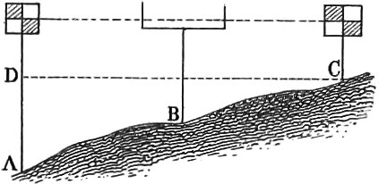 Applied Geometry
Geodesy, or Surveying
Practical geometry, which is itself only a part of applied mathematics, embraces, in a restricted sense, 1, the greater and lesser arts of surveying, or geodesy; 2, descriptive geometry, or theory of proportion. In a restricted sense, we understand by practical geometry only the first of these divisions, which proposes to itself the problem, accurately to determine the size, shape, and position of a larger or smaller part of the earth’s surface, and to represent it pictorially on a reduced scale.
We distinguish, as above mentioned, a lower geodesy or field surveying, which has to deal only with small parts of the earth's surface, as a field, or estate, and a higher geodesy, having reference to whole countries.
Under geodesy are also reckoned, generally, levelling and surveying of mines.
The first problem in field surveying is to mark off a straight line. This is done by means of straight cylindrical staves of wood, from 6 to 8 feet high, and 1 to 1\(\frac{1}{2}\) inches thick, with iron points at the lower end for more convenient insertion into the ground; together with a number of stakes, called also arrows, pickets, &c. Of these staves, A and B are placed perpendicularly in the ground about 100 feet apart, and a third, C, still further forward in the same straight line. In order to place these staves in the same straight line, we may have them so adjusted, that, standing behind A, the others, B and C, shall both be covered by it; or A and B may be covered by C in the line of sight. This latter method is, perhaps, preferable. We must proceed in the same way to extend the line of these staves.
The second problem is to measure a line which has already been staked off. This is done either by means of the measuring chain, which is most generally employed, or by measuring tapes or threads, which are commendable for their cheapness and convenience, but do not afford accurate results; or, finally, by measuring staves, which give by far the most correct measurements.
With stakes and a chain, or some other means of measuring a given line, quite a number of the more difficult problems may be solved, without any other apparatus. We can, in the first place, survey any irregularly curved line on the surface of the ground, as, for instance, the outline of a field or plain (pl. 4, fig. 1). To this end, a straight line, AB, is staked off, and on this as many successive distances, Aa, ab, bc, &c., as possible, measured. The distances, aa′, bb′, cc′, &c., from a, b, c, &c., are next to be measured at right angles to the base (which may be done by the eye, or more accurately with a string divided as the numbers 3, 4, 5, of a right angle). The measured distances of both kinds, the abscissas, Aa, Ab, Ac, &c., as also the ordinates, aa′, bb′, &c., are traced on paper on a reduced scale, and the points, a, b, c, &c, united. The accuracy of the outline will be evidently in proportion to the number of abscissas and ordinates measured. The outline may sometimes be such as to render it advisable to stake off two lines, as in fig. 1, whose relation to each other must be known.
In the second place, the distance between two points may often be determined even when no direct measurement is possible. Three principal cases are here to be distinguished: 1. When the distance between two points cannot be measured directly, but only that from a third point to each of these two (fig. 2). In this case, we measure the distances, CA, CB; continue the prolongations of these lines beyond C, towards D and E; take CE = CA, and CD − CB, or the reverse; the measured distance from D to E will be the same as that from A to B. It is much more convenient, when the prolongations of the lines, AC and BC, cannot be made equal to them, to take a certain part of the distance, as one fourth Cd = \(\frac{1}{4}\)Cb, Ce = \(\frac{1}{4}\)Ca; then de will be the same fraction of AB, or de = \(\frac{1}{4}\)AB, or AB = 4de. 2. When we can reach only one of the two points whose distance from each other is desired, as in pl. 4, fig. 3. Here we assume any point, C, at pleasure, from which B may be reached in a straight line, measure CB, and continue the prolongation of this line to D, so that CD = CB, and then in the direction DE, making the angle CDE = CBA. (To effect this take on BA and BC, any portions, Ba, Bb—five feet, for instance—measure the distance ab, make Dd=Bb, and with a beam compass, from d as centre, with ab as radius, describe an arc, intersecting another arc from D as centre, with aB as radius. Stake off the line DE through e, and we shall then have the direction of the required angle.) We then continue in the direction DE or De until we reach a point, E, which lies in the same straight line with C and A, as ascertained by two staves. The distance DE will then equal AB. Fig. 4 represents another method of attaining the same result: Take on AB any point, C, between A and B, and then a point, D, whose distance from B and C may be directly measured; continue the lines CD and BD beyond D, making DF= CD, DE = DB. Finally, draw EF, and continue it to a point, G, in the same straight line with D and A; EG will be the distance required. We may here also, instead of the whole line, BD, CD, take a fractional part of these prolongations; thus, if we make De = \(\frac{1}{4}\)DB, and Df = \(\frac{1}{4}\)CD, then, if g lie in a straight line with AD, as well as with ef, eg will = \(\frac{1}{4}\)AB. 3. When we can reach neither of the points, A, B (fig. 5). In this case, many methods may be employed; the one represented is perhaps the simplest: lay off the line CD approximately parallel to AB, and on it take cD equal to an aliquot part, as \(\frac{1}{4}\) of CD; make Dca = DCA, and Dcb = DCB, taking the distance ca so that a may be in the line AD, and Db so that b may be in the line BD, then ab will, in our figure, be \(\frac{1}{4}\) of AB (the line cb is not represented).
To determine with staves alone, the height of an object whose foot cannot be reached, we employ two of unequal lengths, DE and FG (fig. 8). Erect the two staves so that the eye, placed at the ground at J, shall see their summits, E and F, in the same line with that of the object, B. The staves being of known height, measure the distances, JD and DG (together equal to JC): with the same staves repeat the operation at another point of the line, J A, as at C and D′, obtaining the values J′D′ and DC′ (together = J′C′). As the triangles JDE, JGF, and JAB, are similar, and also J′D′E′, J′C′F′, and J′AB, as well as GF= C′F′ and ED = E′D′, we will have
JD : DE :: JG : GF
JD : DG :: JA : AB
=JG : GF :: JA : JB :: JG : JA :: GF : AB.
J′D′ : DE :: J′C′ : GF
J′D′ : DE : : J′A : AB
=J′C′: J′A :: GF : AB. But
JG : JA :: GF : AB
=JG − J′C′ : JA − J′A :: GF : AB.
JG and J′C′ are, however, known; JA − J′A = JJ′ is also known, consequently AB = in \(\Large \mathrm{\frac{GF\:\times\:JJ'}{JG-JC'}}\).
The shadow of an object when the sun shines may be used for measuring its height, although this method has no claim to great accuracy. Erect a perpendicular post or staff, of known length, and measure as nearly as possible at the same time, the length of its shadow and that of the object; then the length of the staff will be to that of the object as the lengths of their shadows. If in the line of the shadow we erect a post so that the end of its shadow coincides with that of the object’s shadow, then the same proportions will hold good, and the method is at the same time more convenient (pl. 4, fig. 6).
If the foot of the object to be measured cannot be reached, we may apply the preceding method on two different days, when the sun has a decidedly different height, best of all at the time of true noon, when the shadow falls exactly in the true meridian. If we indicate the length of the object’s shadow at the two different times, by C and C′, those of the post's shadow by c, c′, and the length of the post by a, then the height of the object will be \(\Large \frac{a(\mathrm{C-C'})}{c-c'}\).
Instead of the shadow we may use a horizontal reflecting surface (of oil or mercury). Erect at any point, D (fig. 7), a staff, DE, of known length, not to exceed a few feet; find a place, C, between the staff and the object, where the mirror shall reflect the top of the object to the eye placed at E. In this case, the triangles, CDE, ABC, are similar, and if AC can be measured, the height desired will = \(\Large \mathrm{\frac{AC.DE}{CD}}\), or (substituting c for AC, a for DE, and d for CD) = \(\Large \frac{ca}{d}\). If the foot of the object cannot be reached, the same process may be repeated with the same staff, at another place, D′, and the height will = \(\Large \frac{c'a}{d'}\), if C′D′ = d′, AC′ = c′. If now, CC′ = b, and consequently, c′ = c′ + b, then \(\Large \frac{c'a}{d'}\) = \(\Large \frac{(c'+b)a}{d}\), whence c′ = \(\Large \frac{bd'}{d-d'}\), and the height required \(\Large \frac{ab}{d-d'}\).
The describing of a part of the earth's surface, i. e. making a perfect representation of it on a reduced scale, is to be considered as one of the principal problems in surveying. Three methods may be employed when only a small part, easily overlooked, is in question: in these the plane table is the most convenient instrument to be employed. 1. By sighting forwards and measuring. Sight from a given station A (pl. 4, fig. 9), situated in the inside or in the circumference of the figure, towards all its corners, which are to be indicated by signals or other marks; measure also the distance of this point from all the corners, determine the sight lines on the plane table by means of a diopter ruler, and mark off, according to a scale, the proportional lengths of the distances above mentioned. By connecting the extremities of the lines thus obtained, we shall have a figure similar to that of the field. 2. By going round the figure, or sighting backwards. All the sides of the figure (except two) must be measured, and sights taken from one corner to the others. This is also called surveying the figure from the circumference. The method is inconvenient, but oftentimes the only one practicable (fig. 11). 3. Surveying from two stations. Measure a base line, AB (fig. 9), and sight from its ends to all the corners of the figure; transfer this base, reduced, to the paper, and draw from its extremities the lines of sight: the intersections of these two sets of lines will determine the corners of the figure. This method, when it can be employed, is always preferable to the other two. It is more fully illustrated in pl. 5 (fig. 57). Here ab is the base, which may be 100 or 1000 feet long. After it has been measured, the plane table is set up at A, and from a, sights taken to the other extremity of the line, as also to all the principal points visible from A, as C, D, E, F, &c. The corresponding sight lines are then to be drawn on the table by means of the sight or diopter ruler. The length of the base line is then to be marked off on the sight line running towards b, on a reduced scale, as \(\frac{1}{1000}\) or \(\frac{1}{5000}\); the table removed to B. It is here to be set up in such a manner that the point b lies directly over that part of the base answering to b. It is furthermore erected so that the sight line to a corresponds with the line ab drawn on the table. The points C, D, E, F, &c., already sighted from A, are to be sighted from B, and the corresponding sight lines drawn upon the plane table. Their intersections with those drawn from the other extremity of the line, determine the position of these points on the reduced plane of the table.
If a great surface is to be measured—an entire country, for instance—a trigonometrical net-work must be constructed, as already mentioned under the head of Trigonometry. This consists in dividing the part of the earth’s surface in question, into a great number of connected triangles, whose corners form stations visible one from the other. In these triangles, only one side, rarely over 1\(\frac{1}{2}\) mile long, needs to be measured; in addition to which, the angles must be measured with a theodolite. Care must be taken that the angles of these triangles be neither too acute nor too obtuse; those most nearly equilateral are most convenient. The net must be so arranged that each sheet of the plane table contains at least two of the corners of the trigonometrical net. In pl. 4, fig. 10, AB represents the base; from this the points D and C are determined, by measuring the angles BAC, DAB, and ABC, DBA, and two triangles thus obtained, whose sides, AC, BC, AD, BD, may be calculated trigonometrically. AD may now be taken as base, and the point E determined; as also K, from the base DE, &c. In this manner the network, ABCDEKH, is produced. It will add greatly to the accuracy of the work to determine each point from several stations if possible. This serves to control the various measurements. Suppose the point K to be determined from DH, and likewise from DE, if it should fall towards L, some error must have occurred, which must be detected either by repeated measurements or by special calculations to which we have not time here to refer.
Avery important problem, and one of frequent occurrence, is to determine the point on the plane table corresponding to the one where it was originally set up; this, knowing the positions, α, β, γ, of the three points of the field. A, B, C (fig. 64–68). If the triangles, α, β, γ, can be brought into a position perfectly parallel to the field triangle ABC, then the point required will be determined by applying the sight ruler at α, β, γ, and sighting towards A, B, C; the intersections of these three lines will determine the point. It is very difficult, however, to attain this parallel position. If the two triangles are not parallel, the three sight lines will form a triangle, by means of which the desired point may be attained. We cannot here go into the minute details of the operation.
To determine the area of a rectilineal figure, all that is necessary is to divide it by diagonals into triangles, whose individual areas are to be computed from their ascertained bases and altitudes, and added together. The figure may also be divided into trapezia and triangles, which method is sometimes preferable. When the figure to be calculated is curvilineal, the latter method may sometimes be employed (as in fig. 13), if the parallel lines are drawn so closely to each other that the included parts of the circumference may, without material error, be considered as rectilineal. In the case represented in fig. 12, the two triangles, ABC, BCD, are first calculated, then the mixed lined parts by which the triangles exceed the curvilineal figure. This latter is effected by dividing them into trapezia and triangles, by perpendiculars erected, and subtracting their sum from that of the triangles. In fig. 14, the computations are to be made in the same way, and the sum of the mixed lined portions added to that of the triangles. In fig. 15, the parts BCL, DEK, &c., may be determined in the same manner.
Levelling forms a particularly important branch of Geodesy. This consists in ascertaining the difference in height of two points of the earth’s surface, by direct measurement, and not by projection or calculation. The object of levelling may be thus expressed generally: to ascertain how much further one point of the earth’s surface lies from its centre, than another point. As a general rule, it is not great elevations that are here in question, but simply the gradual rise and fall of the ground. The instruments necessary for this purpose will be described hereafter; the operation itself is explained by pl. 4, figs. 16–19. In general, two methods for determining the difference of height of two points, may be distinguished—either to set up at one of the two points (fig. 16), or between the two (fig. 17): the latter is, perhaps, preferable. The distance between the two points whose difference in height is to be ascertained, must not be very great (from 1–2000 feet). At a greater distance, intermediate stations must be assumed, which the nature of the surface sometimes renders necessary for slight distances. Thus, in fig. 18, the difference of elevation between A and J is to be ascertained by means of the intermediate stations, C, E, G, assumed in the lines A, J; four levellings are here required. In fig. 19, this difference between A and D is determined by means of the two intermediate stations, B and C.
It will be necessary to add, in conclusion, a few words with respect to topographical drawing. This consists in representing portions of the earth upon paper, in their natural appearance. A topographical drawing differs from a chart in its much larger scale, which admits of the insertion of more details. While, for ordinary maps or charts, the scale rarely exceeds \(\frac{1}{20000}\) of the natural size, in special plans for economical or military purposes, it may amount to \(\frac{1}{2500}\), that one line, or \(\frac{1}{100}\) of a foot in the drawing, would represent 25 feet of ground.
A topographical drawing represents not only streams, roads, houses, forests, &c., but also mountains and valleys; and this in such a manner that from the drawing the steepness of the declivities may be ascertained. This is done, according to the almost universally adopted method of the engineer Lehman, by means of rectangular pen strokes, made side by side, in such a manner that the amount of black is to the amount of white, as the given angle of inclination to 45° minus the same angle; consequently, a horizontal surface appears entirely white; that inclined at an angle of 45°, entirely black; at 5, 10, 15, 20° of slope, the breadth of each black space is respectively \(\frac{1}{8}\), \(\frac{2}{7}\), \(\frac{1}{2}\), \(\frac{4}{5}\), of the white interval succeeding; while at 40, 35, 30, 25 degrees in succession, the reverse order takes place. This method is not calculated for slopes of from 45° to 90°, for the simple reason that they seldom occur, are always much broken in their declivities, and are entirely impracticable for military purposes, which the inventor had chiefly in view. Figs. 58–60, on pl. 5, are intended to elucidate the preceding remarks. Fig. 60 represents the environs of the town of Greitz, and fig. 59, the plan and profile of a mountain top, drawn according to the declivities of the surface.
Descriptive Geometry
Projection
Projection in vertical and horizontal planes
By the theory of projection is understood in general, a combination of all those propositions by whose application we are enabled to represent an object as it appears to us in a certain direction, and from a certain distance. If we suppose lines to be drawn from our eyes to all points of the object, representing lines of sight, a pyramid of rays will be formed, whose base is the surface of the object, whose sides are the rays of sight, whose apex is the eye, and whose altitude is the perpendicular distance of the object from the eye. If we suppose a plane to be passed through this pyramid, parallel to its base, according to the principles of similar figures and the laws of Stereometry, we will have an image in the plane of intersection which is similar to the body in question, and which is smaller as the distance of the plane from the eye is less. If we suppose the object to be at an infinite distance, the pyramid produced will be of great altitude, and the angle made by the sight rays with the base of the pyramid will be obtuse; if the section be made tolerably near the base, we may assume the portions of the sight rays thus cut off as parallel to each other, and perpendicular to the base of the pyramid. The intersecting plane is called the plane of projection, and upon it the image of the object is supposed to be represented.
According to the preceding principles we can find the projection of a point, by drawing a perpendicular from it to the plane of projection; the intersection of the line with the plane will be the projection of the point. Nevertheless, as the distance from the plane at which the point is situated is not determined, we cannot ascertain its actual position from this projection. This will be possible, however, if we employ a second plane, upon which we may suppose the distance of the projection from the point itself to be described. The first plane is called the plane of elevation, or the vertical plane; the second, the ground, or horizontal plane. Both planes may be considered as perpendicular to each other, and the position of a point in space may be accurately determined by the intersection of the two perpendiculars erected from the projection of the point on the two planes. In pl. 4, fig. 20, AB is the vertical plane, and BC the horizontal plane; a′b′ is the vertical, and a″b″ the horizontal projection of a line. If we suppose lines to be drawn from the four points, perpendicular to their respective planes, a′ and a″ will intersect each other in ab′ and b″ in b, and the position of the points, a, b, in space will thus be determined. Now whenever two points in any straight line are known, the line itself will be determined.
We can imagine the horizontal plane to be revolved about its axis in such a manner as to form an angle (= 2R) with the other plane, leaving only one plane upon which objects are to be projected. If a line out of this plane is to be projected upon it, perpendiculars must be let fall from the two extremities upon the horizontal plane; the straight line connecting the feet of these perpendiculars is called the projection of the line.
As a straight line is determined by two of its points, and as curved lines require several, every curved line may be considered as consisting of infinitely small straight lines. The projection of a curved line, then, is the same as that of a straight line, only requiring more points in the line. Thus in pl. 4, fig. 23, let 1 2 3 4——9 indicate the position of a line in horizontal projection—we here suppose the horizontal plane to be revolved—and 1′ 2′ 3′——9′ be the position of the line with respect to the vertical plane xy; the projection of the line is now to be found. First of all a number of points is to be assumed in the line 1——9, the same determined in the line 1′——9′, and perpendiculars drawn to the corresponding plane, which determine the feet. Prolong these perpendiculars beyond their feet and they will intersect each other, the points of intersection of the corresponding perpendiculars forming the corresponding points of the projection. Thus, from the intersection of the perpendiculars 3 and 3', the point 32 lying in the projection is ascertained. When all the points are found, the projection will be obtained by joining 12, 22, 32——92, this will be the line.
As surfaces are bounded by lines, we can obtain the projection of surfaces by finding the lines inclosing them. In fig. 21 let abed be the position of a surface in plan, a3 c3 is the position of ac in elevation. To determine the two corners b3 and d3 on this line, project b and d upon ac, in b2 and d2, and take off these points on a3 c3. Drawing perpendiculars from the four extremities of the two horizontal figures, we shall have the points a′, b′, c′, d′ as the corners of the projection, which is itself obtained by connecting the corners by straight lines.
If the figure be bounded by curved lines, a mode of proceeding similar to that employed in the case of straight lines will be necessary. In fig. 22 let ab be the view of a circular plane, in ground plan, f5 f4 the same in elevation. It is well known that the end view of a circle perpendicular to a plane appears as a straight line, this in the ground plan being the horizontal, and in the elevation the vertical diameter. We must thus, first of all, find the points in the curved line which are to be projected. For this purpose describe the two semicircles, divide them into an equal number of equal parts, for instance, in c′, d′, e′, &c., and in a4, c4, d4, &c., and project these upon the diameter; we shall thus obtain the points a, c, d, &c., and a5, c5, d5, &c. By drawing the lines of projection from the like named points, we shall obtain the projected points of half the curved line. Thus, for instance, from the lines of projection from d and d5 we get the point d3, and as d and h lie at an equal distance from the centre, we obtain by means of the lines from h and a5 the point h3 symmetrical with d3. After the points of projection of the upper semicircle have been found, we describe the semi-curve a2 c3——b2, and corresponding to it, the symmetrical half, lying beneath.
Solids are bounded by surfaces, as these are by lines; the problem of finding the projection of a solid resolves itself, then, into finding the projection of points. In illustration of this, we will explain the method of projecting a regular six-sided pyramid, in its various positions. Pl. 4, fig. 24, exhibits this pyramid in its regular position, in a horizontal and vertical plane: acdbef is the polygon forming the base of the pyramid, and which we have placed in the same position in the ground plan, with respect to the bases xy, that the pyramid is to have in elevation. If we suppose the pyramid to be completed above this base, we shall have a view from above of the former. For this purpose, if the pyramid be right, we find the centre of the polygon: this will be the projection of the apex g of the pyramid. Lines drawn from the point g to the corners of the base, form the projections of the edges of the pyramid. To the eye, however, the projection thus obtained will suit for any height of the pyramid, as the point g is not determined with respect to its distance from the base; we must therefore have a side view of the pyramid, since, as already mentioned, two projections, at least, are necessary to determine the position of a point. As the lines which stand perpendicularly to the ground plane are projected as points, under the same conditions surfaces will be projected as lines. The case is the same with respect to the plane of elevation: g is the projection of the altitude of the pyramid in the plane, which appears as a line in elevation; acdbef is the projection of the base in plan, which appears in the plane of elevation as a series of lines, whose position and individual extremities are determined by drawing the perpendiculars aa′, cc′, &c. The position of the point g′, in the perpendicular gg′, is determined by the method already explained. By connecting the point g′ with the points a′, b′——f′, we shall obtain the vertical projection of the pyramid.
Suppose that an oblique section, h′n′, be made through the pyramid, perpendicular to the plane of elevation, and its projection in the ground plane required; the first step will be to indicate the plane h′n′ by a straight line. The lines a′g′ and ag, c′g′ and eg, &c., are corresponding projections. If, then, from the points where the plane h′n′ cuts the different edges of the pyramid in the elevation, perpendiculars be let fall upon the corresponding edges of the plan, the points of intersection will determine the corners of the plane of intersection, h, i, k, l, m, n.
If we suppose the pyramid to rest with one corner, b3, upon the basis xy, as in fig. 25, its axis, however, still parallel to the plane of projection, the projection on the horizontal plane must be changed, as the altitude of the pyramid is no longer perpendicular to this plane. To describe this projection, plaoe the elevation obtained in fig. 24 upon the corner b3, at the required angle, and then draw from the point g a perpendicular to the ground plan. From the point g, of fig. 24, draw a line parallel to the basis xy, until it cuts the perpendicular in g2; then g2 is the apex of the pyramid for the new projection. It is evident that the line gg2 must be parallel to the basis xy, as, according to the assumption, the axis of the pyramid remains parallel to the plane of elevation: the line gg2 is the projection of the circular arc described by the apex g, during the supposed change of position about the corner b3. The same condition holds good for all the other points of the pyramid; and by drawing perpendiculars from points a3, b3——f3, their intersections with lines parallel to xy, drawn from a, b, c——f, will give the points a2, b2——f2, determining the projection of the obliquely situated base: connecting these points with each other, and with the apex g2, we obtain the horizontal projection of the oblique pyramid. In a similar manner we obtain the projection of the plane of intersection, h3 l3, exhibited in the elevation as a straight line: this projection is h2, l2——n2.
Let us now suppose the pyramid to be rotated upon the corner b3, still at the same inclinatic a to the base xy; the axis of the pyramid will no longer be parallel to the plane of elevation. It is evident that all points of the pyramid must describe horizontal arcs during this rotation, whose centres will lie in a perpendicular, supposed to be erected from the point b2. Their perpendicular distance from the base must, consequently, remain the same as before. As, however, the inclination to the base remains the same, the projection in the ground plane needs to be changed only with respect of the direction of the edge g2b2 to the base xy. Pl. 4, fig. 26, represents the upper view seen in fig. 25, at the same angle with the basis xy. The preceding explanations have taught us that we can draw horizontal lines from all points of the elevation, in which the new projections of these points, for the new position, must lie. The points are absolutely denned, by drawing perpendiculars from the corresponding portions of the plan to these horizontal lines. Thus, to obtain the position of the point g4 in the new projection, we draw the horizontal lines g3g4 and the perpendicular, g2g4 In like manner we obtain the projection of the base a4, b4——f4 and consequently the projection of the entire pyramid, by uniting g4 with these corners. As this pyramid is no longer parallel to the base, the plane of intersection, h3l3 (fig. 25), can no longer appear as a straight line in this last position of the pyramid. Its projection, h4, l4, k4——n4, is obtained by the preceding methods.
As an additional illustration, we give the projection of the three principal conic sections. If we imagine a plane to be passed through a cone, which is parallel neither to the axis nor to one of the sides, we shall obtain a regular, symmetrical, curved line, teemed an ellipse; if the plane be passed parallel to one side of the cone, a parabola will be produced; and when parallel to the axis, a hyperbola. The development and properties of these three curves are cases of the higher Geometry and Analysis (see pages 24, 25). In this place we have to do only with their projections.
Pl. 4, fig. 27, is the projection of a right cone in the horizontal and vertical planes. The circle, A′B′, and the straight line, AB, are the projections on the vertical plane of the base, C is the apex, and DE the intersecting plane, appearing in elevation as a straight line, and whose intersection is to form the ellipse, whose shape in horizontal projection is to be obtained. The question reduces itself to finding the breadth of the ellipse for the different points of the circumference. These points lie symmetrically upon the surface of the cone, only in different planes above the base; and it is necessary to find the projections of these planes in both views of the cone. In the vertical projection, these planes appear as straight lines; in the horizontal plane, as circles. When we pass planes through D and E, in the vertical projection, the points D and E, of the curve, will be situated in them; if, then, the length DE be divided into any number of equal parts, and horizontal planes be passed through the points of division, there will be two points of the ellipse in each plane, which will be situated in that part where the line DE cuts these planes in succession. To obtain the form of the ellipse in the horizontal projection, we draw in it the diameter, A′B′, and let fall upon it perpendiculars from the points 1.2. . . . DE: the points 1′, 2′, &c., will answer to the horizontal projection of those points, and as the horizontal projections of the surfaces projected as straight lines in elevation must be circles, these can readily be determined, knowing their radii, C′, I′, &c., and their common centre, C. These circles are cut successively by the ellipse. By drawing the perpendiculars, DD′ and EE′, we obtain the projection of the extremities, since the axis of the ellipse lies parallel to the plane of projection. Drawing a perpendicular from the point where the ellipse cuts the plane marked 6, until it cuts the circle 6′ in the horizontal projection, we shall obtain one point of the horizontal projection of the ellipse, or two as the ellipse is symmetrical. By a repetition of the process, a number of points in the horizontal projection will be obtained, through which the ellipse itself may be passed. The figure standing near fig. 27, exhibits the actual view, or the orthographic projection of the ellipse. It is obtained by taking off the axis, DE, of the ellipse from the vertical projection, with its planes of intersection, which would here be represented as straight lines. From the horizontal projection, we obtain the true breadth, and if these be described one after the other upon the corresponding planes on each side of the axis, we shall obtain the points through which the ellipse is to pass.
Pl. 4, fig. 28, exhibits the vertical and horizontal projection of a right cone, with a parabolic intersection. DE is the projection of the parabola, which, for the vertical plane, is a straight line. The horizontal projection is obtained precisely as in the case of the ellipse. Thus, 1, 2, 3, — — — horizontal planes are passed through that part of the front view of the cone traversed by the parabola, at equal distances from each other; these appear as straight lines: they are circles in the horizontal view of the cone. In fig. 28, semicircles only are drawn. From the points, 1′, 2′, &c., where the planes passed through the elevation cut the parabola, draw perpendiculars to the horizontal projections of these planes; the perpendicular, DD′D″, will form the foot of the parabola, EE′ its vertex, and perpendiculars from 1′, 2′, — — — let fall upon the cirles 12, 22, 32, — — — will form intersections, all lying in one arm of the parabola, the other being easily constructed, as shown in fig. 28. The orthographic projection of the parabola is shown in the figure near fig. 28. It is obtained by erecting a perpendicular from the middle of DD′, and marking successively upon this the height D1′, D2′, D3′, &c., and drawing throngh these points, parallels to DD′. Marking off on these horizontal lines, the breadths taken at the corresponding parts of the horizontal projection of the parabola, we shall obtain the points, 1′, 2′, 3′, 4′, and 5′ E, which determine one half of the parabola. The other half is to be drawn symmetrically with this.
A simple method of describing a parabola, when its breadth below and its altitude to the vertex are given, is shown in fig. 31. At the middle of the line AB, erect the perpendicular, CD = twice the height of the parabola, and determine the vertex, C; through this xy is passed, parallel to AB. At A erect the perpendicular, Ax, and divide it in f, g, h, &c., into equal parts, which are then marked off from D, at a, b, c, &c. From C to k, and from A to a, draw straight lines; their intersection will give one point of the parabola. Another point will be obtained by the lines Ci and Ab, &c. The second limb of the parabola, being symmetrical with the first, is easily constructed.
The projection of the third conic section, the hyperbola, is explained by means of fig. 30. As this is perpendicular to the base, it can appear only as a straight line in horizontal projection, this line being D′F. The vertex is projected at E′. If the line E′F′ were also perpendicular to the base line, the hyperbola would be projected on the vertical plane in another straight line: this is the case in fig. 55, with respect to the line CA. As this view can give no satisfactory representation, we have in fig. 30 made the plane of intersection parallel to the vertical plane. To determine the vertex of the hyperbola in the vertical view, we first draw the axis, CC′, take off from C, and parallel to the base, the distance C′E′, and let fall from the point thus obtained, a perpendicular to the side of the cone. From the point where this meets the side, draw to the axis a parallel to the base; this determines the point E on the latter. Place any number of planes of intersection, in the horizontal projection, parallel to the base; these will form circles with the common centre C′ and whose vertical projections as straight lines may be readily ascertained by methods already explained. From the points 1, 2, 3, &c., of the ground plane, where the projections of the intersecting surfaces cut those of the hyperbola, draw perpendiculars to the corresponding vertical projections of the aforesaid planes of intersection; we thus obtain the intersections 1′, 2′, &c., as points of the hyperbola, which may then be joined by a line continuous with the vertex E. Another method of describing the hyperbola is presented in pl. 4, fig. 29.
If one body penetrate another, a surface of intersection or penetration will be formed. It is one of the problems of projection to determine the outlines of such surfaces of intersection, and their projections under different circumstances. The number of possible cases is infinite, and we can here only adduce a few as examples. In fig. 32, two cylinders are shown, of unequal diameters, and penetrating each other at right angles. The base line, or the one in which the surfaces of horizontal and vertical projection intersect each other, may be represented by xy. The one cylinder is represented in vertical projection as circle E, and in horizontal projection as rectangle AB; the other, being parallel to both planes, is in both cases exhibited as a rectangle, until it touches the second cylinder; the problem, therefore, is reduced to rinding the part which intersects the surface of the first cylinder. In vertical projection this is easy, as here the line of intersection coincides with the convexity of the cylinder; nothing more is necessary, then, than to prolong the corners a and g to the cylinder E. The case is different, however, in the horizontal projection, the line of intersection here being a curve. If the axes of the two cylinders lie in the same plane, the curve will be symmetrical; if, as in our example, this is not the case, the superior half will be different from the inferior, and it becomes necessary in all cases to seek similarly situated points of the intersection surface, in the horizontal and vertical projection. For this purpose, under ag and a′g′, describe the semicircles whose projections are the lines ag and a′g′; divide their circumferences into any number of equal parts, and draw lines parallel to the edges of the small cylinder. These must reach to the circumference of the larger cylinder, in the vertical projection, and may be of any length in the horizontal. From the points where these lines intersect the circumference of the larger cylinder in the vertical projection, let fall perpendiculars upon the corresponding parallels in the horizontal projection. We shall thus obtain the points h, i, k, l, m, n, and o, which are common to the convexities of both cylinders, and must consequently lie in the contour of the surface of intersection; this latter may then be easily described. We have represented the lower half of the curve; the upper is obtained in a similar manner. As the cylinders approach towards equality in thickness, the curve becomes abrupt; when both are equal, the intersection appears in the projection as two straight lines, which meet above the axis of the cylinder.
Pl. 4, fig. 33, represents the intersections of two cylinders, of different diameters, when their axes lie in the same plane. The mode of constructing the cylinders and their bases follows from what has already been said. We must remark, however, that the two upper ellipses in the vertical view have arisen from a misapprehension of the engraver; the upper bases should have been projected as straight lines. The construction of the intersection follows from what was said in explanation of fig. 32. With respect to the horizontal projection, the views of the bases are readily found, these being ellipses, whose perpendicular axes are the respective diameters of the cylinders, the horizontal being determined from the vertical view, by means of the perpendiculars gg′, hh′, ee′, ff′, aa′, bb′, cc′, & dd′. To project the line of intersection, the points of division of the projection ef are projected upon the ellipse ef, at 1′, 2′, &c., parallels to the surface, drawn through the points of the ellipse thus obtained, and at the corresponding points the line of intersection in the vertical view, cut by perpendiculars. The points of intersection will be common to both cylinders, or be points in the line of intersection. The lower line of intersection, dotted only in the figure, is obtained in a similar manner.
Fig. 34 exhibits the intersection of a cylinder and a sphere, where the cylinder has the smaller diameter of the two, and is not parallel to the surface of projection. The development of both projections presents no difficulty in itself, if what has already been said on the subject be kept in mind; it is only the circumferences of the surfaces of intersection that require to be attended to here. These surfaces of intersection must, in all cases, be curves : they are obtained by dividing the circumference of the cylinder into any number of equal parts, and, through these, drawing parallels to the sides of the cylinder. The figure represents only a few of these parallels. Where these lines intersect the perpendicular diameter of the sphere, in the vertical view, planes of intersection are to be passed through the sphere. These can be very readily transferred to the horizontal view, where they appear as circles. The points where the parallels to the circumference of the cylinder intersect the corresponding circular sections, are points of the surface of intersection, which may then be readily described. On account of the small scale of our figure, only a few points have been determined; the rest are readily formed in the same manner. A concluding example of the intersection of bodies is presented in fig. 35. Here, an oblique cone penetrates an oblique cylinder, in such a manner that part of the cone passes through the cylinder. To develope the intersection, the method employed in reference to fig. 33 must be again brought into play, with this difference only, that the lines drawn from the points of division of the base to the cone must not be parallel to the lateral edges, but converging to the apex of the cone.
The reticulation of bodies, and the unfolding and development of surfaces
By the reticulation of a body is meant the continuous description of its inclosing surfaces in one plane. This is easiest in bodies which are inclosed entirely by plane surfaces, as is the case in the so-called regular bodies. It is only in this case that the reticulation of a body can exhibit a perfectly true picture of its surface. Plate 4, fig. 49, is the reticulation of a tetrahedron, formed by four equal equilateral triangles; fig. 50, that of a cube, or hexahedron, formed by six equal squares; fig. 51, that of a dodecahedron, formed by twelve equal regular polygons; fig. 52, that of an icosahedron. The figure is not quite complete, as in addition to the fourteen equal equilateral triangles, six more must be added, viz. one in the upper row, next to 11, three in the middle row, next to 7, and two in the lower row, next to 14.
In conclusion, we will present one or two examples, in which not the entire reticulation, but merely the convex surface, will be referred to. The bottoms, so to speak, are very easily constructed.
Fig. 53 represents, at A, the horizontal intersection of a cylinder by the plane CD, this latter being itself visible in fig. 54. Let portions be cut off obliquely from the lower part of the cylinder, by the lines BC and BE, and an oblique portion from the upper part by the lines FG. Suppose, now, that half the convex surface of this remnant of the cylinder is to be ascertained. If the cylinder had not been mutilated in this manner, its development would be a rectangle, the altitude being equal to the height, and the base equal to the circumferenee of the cylinder, or, as in our illustration, to half this circumference. This rectangle must, in fact, oe constructed upon the elements first mentioned. The semi-circumference, in fig. 53, is to be divided into 8 equal parts, as shown at a, b, c, d, &c.: these must be so small that, without material error, the arcs may be considered as straight lines. These eight parts are to be transferred to the rectangle at a2, b2, &c., and the perpendiculars a2a3, b2,b3, — — — i2i3, drawn, which will all lie in the convex surface of the cylinder. From the points a, b, c, — — — i, in the horizontal projection of the cylinder, lines are to be drawn until they intersect the oblique section of the cylinder at a′, b′, — — — i′, From the points a′, b′, — — — i′, draw parallels to the base, xy, until they intersect their corresponding lines; the points a3, b3, c3, — — — i3, will thus be obtained, which may be connected by a curve. This will be the development of half the ellipse of which the line FG represents the vertical projection. The perpendiculars aa′,bb′, — — — ii′, also intersect the projections CB and BE of the semi-ellipses of the lower cylinder sections; accordingly, here, as in the upper ellipse, the corresponding points may be connected by parallels to the base, xy, and points of the curve obtained on the lines a2a3, b2,b3, — — — i2i3. Fig. 54 represents rather more than half the development of the cylinder.
Fig. 55 exhibits the horizontal and vertical projection of a right cone, intersected in the three conic sections, and projected according to the rules given for figs. 27, 28, 29. The convex surface of this cone is now to be found, and upon it the developments of the three conic sections, described.
The convex surface of a right cone is a circular sector, whose radius equals the slant height of the cone, and whose arc equals the circumference of the base. If, then, from any point, with a radius equal to the slant height of the cone, an arc, x2y2 (fig. 56), be described, this sector, with its two radii, will determine the convex surface of the cone, provided that the proper length of the arc has been obtained. This may be done by dividing the circle whose projection is xy (fig. 55), just as was done in the case of fig. 53, and transferring the arcs of division. The sum of these arcs, which will be few or many as the result is to be less or more accurate, will determine the extent of the circumference of the base. Lines drawn from the individual points of division to the centre, in fig. 56, will represent so many lines of the convex surface of the cone. Their projections in elevation (fig. 55) will be obtained by transferring the parts from the plan, x′y′, of the base, to its vertical projection, xy, by means of perpendiculars. Lines must then be drawn from the points of intersection thus obtained, to the apex. These will intersect the vertical projections of the conic sections.
From the vertex, in fig. 56, lay off on the middle line the distance from the apex of the cone (fig. 55), to the point G′; G′ will then be a point in the development of the ellipse. The distance from the apex of the cone (fig. 55) to the first intersection of the ellipse by the projection of the sides of the cone in fig. 55, laid off on both sides of the point G2 in fig. 56, gives two new points in the development of the ellipse; and the same is to be done with respect to the remaining lateral lines of fig. 55. Connecting these points in fig. 56, will give the development of the ellipse. In like manner the curve B2A2C2 is found, as the projection of the hyperbola. The parabola, in its development, appears divided into two symmetrical parts, owing to its falling on the line in which the convex surface of the cone is supposed to be divided. By these various constructions, we obtain the symmetrical figure, H2E2F2B2C2A2D2E2H2G2, which forms that part of the convex surface of the cone bounded by the three conic sections.
Projection of Shadows
By projection of shadows is to be understood the method of representing bodies as they appear to an observer under illumination from a certain direction. It is evident that both the direction and the nature of the illumination (whether from a point or a surface) must greatly influence this mode of representing objects. If the illumination be supposed to proceed from a single point, it involves a department of the subject which will not be treated of in this place, as it more properly belongs to another part of our work. We here treat only of that description of shadows produced by an infinitely great luminous surface, considered as the source of light. In the former case, the rays of light form a cone, and diverge the more the nearer the source of light (the apex of the cone) lies to the object illuminated. In the latter case, and the one to be now treated of, the rays are all parallel to each other. In what follows, we suppose the plane of illumination to be so situated with respect to the surface of representation) as that all the rays come in the direction of the diagonal of a cube, i. e. incident at an angle of 45° on both the horizontal and vertical plane. The rays of light are supposed to come over the left shoulder, and to fall upon the paper and the object to be represented.
The general head of shadows embraces two subdivisions, viz. shadows proper and shades. The shade of a body is that part of its own surface from which light has been intercepted by some other part of the body itself. The shadow of a body is that part of indefinite space from which light is excluded by the body. The shadow on a body is that portion of its surface from which light has been intercepted by some other body, placed between it and the source of light.
With respect to the shades of bodies, it is evident that the rays of light can exert their greatest powers of illumination only when they fall at right angles upon a surface, and that the illumination will be less, the more oblique the angle of incidence. The deepest shade must be produced where the rays are only tangent to the body, as they there no longer illuminate the body. Taking for illustration a half cylinder, as exhibited in horizontal projection in pl. 4, fig. 38, the line bb′ will be perpendicular to the surface, and the illumination of the cylinder will consequently be greatest in this part. This is the point of highest light. The ray of light dd′ will only be tangent to the circumference of the cylinder: here then will be the darkest shade. Between b′ and d the rays of light will fall more and more obliquely, and the illumination become less and less. The same must be the case from b′ towards a. Beyond d the body would be entirely dark, were it not for the reflection of light from other bodies about or beyond this. The body will therefore become again somewhat lighter, after its darkest shade. Similar conditions must be presented in respect to the illumination of all other surfaces, and it will not be difficult to determine the tone of light of each surface, knowing the direction of the incident rays. It is evident that by taking this direction at other angles, any other illumination may be constructed. It must not be forgotten, however, that the angles of incidence upon the two planes of projection must always be complements of each other, so that light, incident at an angle of 40° upon the plane of elevation, will strike the horizontal plane at an angle of 50°, &c.
Shadows, as already mentioned, are produced when one part of a body projects beyond another, or one body is interposed between the source of light and another body. These shadows, like the bodies themselves, may be constructed when the measurements of all the parts are known, i. e. the body itself, with all its accompaniments, may be constructed in plan and elevation. The rules for the reception of light must always be the same as in the case of shades, and the same angle of incidence of the light must be employed for both the shades and the shadows.
When a shadow is to be determined, it is, first of all, necessary to determine the lines which cast the shadow; and after these have been found, to seek the projections of these lines of shadow. After this, those parts of the entire surface from which light is intercepted may be readily determined.
Shades and Shadows upon Plane Surfaces and Curved Surfaces of Elevation
Let us suppose figs. 36–44, pl. 4, to represent the vertical, and beneath this the horizontal projection of a plane wall, to whose anterior face six bodies, of different forms, are attached, and covered above with partly circular, partly rectilineal plates: let now the problem be, to determine the shadows cast by the plates upon the solids, and by both plates and solids upon the wall.
Fig. 36 is a four-sided prism, A, covered with a somewhat projecting plate, B, likewise four-sided. To find the various shadows, it becomes necessary first to find the line of shadow. The direction of the rays of light is here, and in the following cases, assumed at 45°, for the horizontal and vertical projection. Draw lines in the horizontal projection, in the direction of the rays, to the bodies A′ and B′; then the first rays passing by the body will go through the points c and d. These are the projections of the two right edges of the bodies A and B, in vertical projection; the latter will therefore be two lines of shadow. If, moreover, rays be drawn at an angle of 45° in the vertical projection, one will pass by at a′ and others at c2 d2, d3: the line a′d2 will consequently cast a shadow. As c2 is the projection of the upper right hand edge of the prism, d2 that of the lower right hand edge of the plate, and d3 of the upper right hand edge of the same, the four lines just mentioned will cast shadows. Of all these edges, the line a′d2 alone casts a shadow upon A; all the rest, and even a part of a′d2, cast shadows upon the wall only.
As the direction of every line is determined by several points lying in it, to determine the boundary of shadow in both projections, we need two points for a straight line, and a greater number for curves.
The shadow of the line a′d4 falls upon the body A, and it becomes necessary to obtain the point b2, from which the shadow must run parallel to the shadow-casting edge, the two surfaces of the body and the plate being parallel. In any case, the point which casts its shadow upon b2 must lie in the line a′d2, whose horizontal projection is ad, and this, in a direction of 45°. If, therefore, in the horizontal projection, a line be drawn from the left corner of A′ to ad, at an angle of 45°, it will determine b as a shadow-casting point. This point is then transferred to the vertical projection, by means of the perpendicular bb′, and b′ is then exhibited as the shadow-casting point in the latter. Drawing a line from b′, at an angle of 45°, its intersection with the left edge, b2, of the prism determines the shadow of the point b′, and the direction of the line of shadow. As the line a′d2 determines the boundary of the surface which prevents the incidence of light upon the body, A, that part of A above the line passing through b2, lies in the shadowed portion.
With respect to the shadows cast by the prism and plate upon the wall, the edge a casts a shadow, which necessarily begins in the point where this edge touches the wall. Drawing a line from a′, at an angle of 45°, this line, a′a2, will be the line of shadow. The side of the plate behind the line d2d3 will likewise cast a shadow, whose direction is determined by the two lines drawn at an angle of 45°, in the vertical projection. The length of this shadow is obtained by considering that the point d, the horizontal projection of the line d2d3, and consequently the edge which is projected through it, casts its shadow to d′. The edge a′d2 also casts a shadow upon the wall, which must run parallel to the edge, the edge and the wall being themselves parallel. The point d4 is the point of shadow for d2; if then, through d4 a parallel to a′d2 be drawn, this will be the line of shadow of the plate on the wall behind it Finally, the side of the prism lying behind c casts also a shadow upon the wall, whose limits will be the shadow of the edge which is projected through c. If then the tangential ray cc′ be drawn, and the point c′ be projected on the vertical plane, the perpendicular through this point will determine the line of shadow, whose upper point still remains to be determined. The point c2 in the vertical projection answers to c in the horizontal; then, if we draw a line, at an angle of 45°, through c2, it will intersect the above mentioned perpendicular in e, and this point, e, will be the shadow of c, or, what is the same, of c2, and will limit the shadow of the edge of the prism.
Pl. 4, fig. 37, exhibits the half of a hexagonal prism, covered by a foursided plate, under the same conditions as in the preceding case. The shade of the body is found according to the principles already laid down. The surface receives the strongest light to the left, the rays here falling perpendicularly; the light, however, fades somewhat towards the extreme left.
The anterior surface receives the light more obliquely, and thus appears somewhat darker and uniformly illuminated, the surface being parallel to the plane of projection. The light passes entirely by the right surface, which consequently appears entirely dark, brightening a little, however, towards the wall, where it receives a certain amount of reflected light. The shadows on the wall are constructed as in. fig. 36; those cast by the plate on the body, are obtained as follows: that for the anterior surface is obtained, as in fig. 36, by the lines bb′, b2b3, as this surface is parallel to the surface of representation, and to the anterior surface of the incumbent plate. The shadow cast by the corner a of the plate, will be determined by a ray of light passed through the point. It will fall upon the left lateral surface at a2, which will therefore be the projection of this shadow. To obtain this point in vertical projection, draw the perpendicular a2a3, and intersect this by a ray through a, a3 will be the point desired. If this be connected with the extremity of the shadow or the anterior surface, the broken line through a3b3, gives the shadow of the anterior face of the plate. Since a is the projection of the horizontal lateral edge of the plate, it follows that every ray through that edge must be parallel to aa3; the direction of the shadow, therefore, from a3 towards the left, will be regulated by that of the ray.
Fig. 38 represents a half cylinder, covered by a four-cornered plate. The shade of the body is obtained by drawing a line from the left-hand side to the centre, at an angle of 45°. Where this line cuts the convex surface of the cylinder, the light will be greatest, the rays falling here in a plane perpendicular to the surface. A second ray, tangent to the surface, determines the line of deepest shade, up to which the light decreases more and more, and beyond which reflected light comes into play. The shadows of the body and the plate on the wall are obtained as before. The shadow cast by the plate on the body must be a curve, the body itself being curved. To obtain this shadow, find first the shadow of the point b, the corner of the plate, which is done by means of the lines bb′, b2b3. As it is a curve that we are seeking, it will be necessary to obtain a number of points in it, so as to determine its direction. The points casting shadows lie, however, in the line be. One of the points of shadow is given by the line cc′, c2c3, and as many more can be obtained as is necessary for the required degree of accuracy. The shadow naturally ceases where the ray, dd′, is tangent to the cylinder: the shadow then passes into the shade of the body. To find the direction of the shadow from b 3 to the left, seek first the shadow of the point a. This falls at a′, and the vertical projection of this point must lie on the line a3. But b2 is the projection of the left side of the plate; the point a3 lies, therefore, behind b2, and if a ray be passed through b2 (actually through d2), it will determine the point a2. This lies in the line b2b3, and all the other points of the shadows cast by the lateral edge will fall in the direction b2b3.
Pl. 4, fig. 39, represents the half of a hexagonal prism, covered by a semicircular plate. The shade of the body has been already constructed in fig. 37, as well as the shadow of the body. It now remains to determine the shadow of the plate on the wall. As the plate is circular, its shadow must be a curve. The method of finding this curve is easily determinable from the preceding considerations. Take a certain number of points in the horizontal projection, obtain their shadows in this projection, and transfer them to the vertical projection. Thus, the point c will cast its shadow to c′, and this must lie on the perpendicular line, c′c3, of the vertical projection; transfer the point c to c2, and from this point draw the ray c2c3; we thus obtain the projection of the point of shadow; and after a sufficient number of points has been obtained, an indication of the curve of shadow produced by the lower edge of the plate. As the upper edge must cast a similar shadow, this is to be obtained in the same way. The point d3 determines the extreme point of this curve, which is closed by a perpendicular representing the shadow of the vertical edge or line of shade of the plate. The shadow of the plate upon the prism must also be curved, as it falls from a curved upon a plane surface. First of all, it is necessary to find the point of shadow upon the edge. For this purpose, draw the line aa′ in horizontal projection; we shall thus obtain the shadow-casting point, a2, in the vertical projection, and a3 as the point of shadow. According to the method described in fig. 38, the points b3, c3, &c., are then obtained, and consequently the curve of shadow upon that side of the prism which lies in the light.
Fig. 40 exhibits the half of a truncated cone, covered by a four-sided plate. The construction of the shade of the body, and the shadow of the cone and plate upon the wall, differs very little from what has been described in fig. 38; it is different, however, with respect to the shadow on the cone. This shadow is analogous to that of the cylinder; as, however, the surface of the cone is not perpendicular, but deviates every moment from the perpendicular, its shadow must fall somewhat differently. To obtain this shadow, suppose several horizontal planes to be passed through the vertical projection of the cone, appearing in it as straight lines, and in the horizontal projection as semicircles; they are indicated by the figures 1, 2, 3, &c. Suppose the rays necessary for producing the shadow to be drawn in the horizontal projection, they will intersect the cone, and as the sections are parallel to the axis of the cone, these sections will appear in the vertical projection as hyperbolas, or at least parts of such, and may be constructed according to fig. 30. These hyperbolas serve instead of the perpendiculars employed in fig. 38, and by means of them, and of the projections of rays as bb′, b2b3, the curve of the shadow may be very readily determined.
Fig. 41 represents a half cylinder, covered by a semicircular plate. Here one plane casts a shadow upon another parallel to it; the shadow will therefore be parallel to the shadow-casting line, and to determine this shadow nothing more is necessary than to pass a ray through the corner where the shadow begins. From the point where this ray intersects the edge of the cylinder, draw a line parallel to the plate: this will be the line of shadow.
Innumerable cases might be adduced, but the general principles involved in all are nearly such as have been explained and illustrated in the preceding instances.
Shades and Shadows upon hollow, straight, and curved Surfaces
Fig. 42 exhibits a four-cornered niche., closed above. The point a is the horizontal projection of the shadow-casting line, and must itself be the shadow-casting point. Passing a ray, aa′, through this point, it will determine the situation of the point of shadow upon the back wall, whose projection in elevation may be determined by the lines a′a3, and a3a2 at a3. As, however, a is the projection of the entire shadow-casting edge, the limit of shadow for this edge must lie in the perpendicular a′a3; a parallel, therefore, to the corner of the niche, drawn through a3, will determine the shadow of the cover.
Fig. 43 represents a niche, forming the half of a hexagon, and covered rectilineally above. The ray of light, aa′, determines the extremity of the shadow in horizontal projection. The intersection of the perpendicular a′a3, with the ray through a2, determines its position, a3, in elevation. The part of the perpendicular below this point, a3, will be the line of shadow cast by the vertical edge of the niche. As the right side of the niche is oblique to the surface of representation, the shadow must run obliquely from d3; now, as the cover coincides with the edge of the niche in c, the shadow must run in this direction; d3c will therefore be the line of shadow on this oblique side.
Fig. 44 exhibits the half of a hollow cylinder, open above, and the problem is, to find the shadow cast by the edge of the cylinder upon its inner surface. Its boundary in vertical projection is obtained, in the first place, by passing a ray through the point a, the horizontal projection of the edge of the cylinder. The vertical projection of the point a′, where it meets the inner surface of the cylinder, is obtained at a3, by the intersections of the lines a′a3 and a2a3. A part of the upper edge of the cylinder also casts a shadow. This begins in the point c2, which is the vertical projection of the point c′, where a ray is tangent to the surface of the cylinder. The point c′ is obtained by drawing a line from c to the surface of the cylinder, at an angle of 45°. The shadow runs from c2 to a3 in the curve. This curve is found by obtaining individual points, as before explained.
Pl. 4, fig. 45, exhibits the shadow of a straight cover to a semi-cylindrical niche. The straight part of the shadow is obtained as in the preceding case; the figure itself shows the method of finding the shadow of the covering. Thus for instance, the shadow of the point b is obtained by means of the lines bb′, b2, and b3, and the shadow ends in the point c′, where the anterior edge, a2c′, of the covering, meets the wall of the cylinder.
Fig. 46 explains the method of finding the shadow cast upon its inner surface by the edge of a niche, dome-shaped above. This shadow has a very peculiar outline, and can only be determined for the dome by a very exact projection of the rays, and the accompanying subsidiary lines. The limit of the straight part of the shadow is easily found to lie at a, according to fig. 45; the extremity of the compound shadow must necessarily lie at e, where a ray of light would be tangent to the dome. To obtain the curve between a and e the following method is to be employed, which is quite analogous to those already mentioned, and peculiar only in the construction of the perpendiculars, by means of which the vertical projection of those points is found, whose horizontal projection has already been ascertained. These perpendiculars, which in all the other constructions have appeared as straight lines, here present themselves, in the space of the dome, as curves. To determine this curvature, horizontal sections are passed through the vertical projection, at 1, 2, 3, &c., projected as straight lines here, but as semicircles in the horizontal view. Suppose in the ground-plan a ray to be passed from any point in the anterior edge of the dome, against the inner wall; this will intersect the projections of all the above mentioned horizontal projections. It will then be easy to determine, from the preceding observations, the vertical projections of these intersection lines, which will be straight to the commencement of the dome, and will then curve according to the curvature of the dome. If these lines be intersected by a line, at an angle of 45°, from the vertical projection of the point from which the ray has been drawn in the horizontal projection, we shall obtain one point in the curve of shadow; the other points necessary fully to determine this curve, may be obtained in the same manner.
Fig. 47 teaches the method of finding the shadow cast upon the inner wall of a dome-shaped, closed, half-round niche, where a part of the dome is cut away above, and the niche continued in a semi-cylinder. This is a combination of the cases treated in figs. 44 and 46, so that it would merely be necessary to construct two shadows, one after another, but for the fact that a part of the dome (that lying between b′ and c′), has been cut out. Here it is not the contour of the dome that casts the shadow, but the boundary of the section. In this manner a part of the shadow seen in fig. 46 is cut away, as shown in fig. 47.
It is necessary, before concluding these remarks on shades and shadows, to advert to the cases where the body is not attached to a wall, but stands at some distance from it. Although these cases present now no difficulty whatever, it may be advisable to give an example, as in fig. 48. Let a six-sided prism stand in front of a wall, as shown by the horizontal projection of fig. 48. The problem is, to ascertain the shadow cast by the pyramid, in horizontal projection upon the floor, and in vertical projection upon the wall behind. First, to find the point where the apex g casts its shadow. Draw rays from g and g′, in horizontal and vertical projection, and combining them in the usual way, find their intersection at g3, the vertical plane. The line g′g3 is the projection of the shadow of the axis of the prism, and g′ is a point in this shadow. We obtain the shadow-casting point of the axis by drawing a line to that axis, from g′, at an angle of 45°. If a horizontal plane, d2b2, be passed through g4 this plane will be projected in plan as a small hexagon. Pass tangent rays to this hexagon; they will determine the points d′ and b′ as the projections of the shadow-casting points of the pyramid, in horizontal projection. If then from d and b the lines dd′ and bb′ be drawn, these will determine the outline of the tapering shadow of the pyramid. The lines d′g3 and b′g3 will determine the outline of the shadow in the vertical view, as is clearly shown by drawing the rays d2d and b2b′.
Linear Perspective
We shall here confine ourselves to the mathematical principles of perspective, as occasion will be had to speak of perspective in general and its application to the arts, in another part of the work.
We have already remarked, in the introduction to projection, that in perspective the visual rays are all supposed to proceed from one point—the point of sight; while in projection they are supposed to be parallel to each other. We may here again employ the illustration of the plate of glass interposed between the spectator and the object, and upon which the perspective image of the latter is represented.
In fig. 57, pl. 4, let XY be the ground plan upon which a square, abcd, is supposed to be drawn, and whose perspective representation is to be obtained on the vertical glass plate RS. Let F be the station of the observer, and A the point from which he sees the square abcd. This point is called the point of sight. The distance of the observer from the glass plate—the plane of projection or the plane of the picture—is determined by the line AA′; the point A′ is called the point of distance. If visual rays be drawn from the point of sight to all the corners of the square abcd, these must necessarily intersect the glass plate or the plane of the picture. It is then necessary to find the points of intersection, so that by joining them by straight lines the perspective of the square may be obtained. For this purpose, in the horizontal plane draw perpendiculars through the points a, b, c, d, extending to the foot of the glass plate. In the position of the square here assumed, two such lines are all that is necessary, as two of the corners lie in one line. Drawing lines from f and g to A′, these must lie in the plane of the picture, and the same must be the case with their intersections with the visual rays. The points a′, b′, c′, d′ will then be the perspective representation of a, b, c, d, the corners of the square. By properly connecting the points a′, b′, c′, d′, by straight lines, the quadrilateral thus obtained will be the perspective of the square.
The line DD′ supposed to be drawn at a height equal to that of the point of sight A, is called the horizon of the picture : it is the principal line in a picture, as by its height all the parts of the picture are regulated. All visual rays tend to the point of sight, and lines perpendicular to the plane of the picture will have their perspectives all tending to the point of sight. The point of sight is also called the vanishing point, because in it the lines appear to vanish. Other parallels not perpendicular to the plane of the picture meet in the horizon, but not in the point of sight. There may, therefore, be several vanishing points in the same picture, but only one point of sight, since an object for one and the same picture can only be observed from a single point.
The preceding construction, however satisfactorily it illustrates the principles of perspective, is yet too complicated in practice; simpler constructions therefore become necessary.
Fig. 58 exhibits a simplified construction for representing the square just mentioned. Let xy again be the basis of the plane of the picture, lying then above this line; the space below xy is the ground plane upon which the square abed is described, and which rests immediately against the basis. We assume for the first case that the point of sight A is opposite to the middle of the square, and that DD′ is the horizontal line. The distance of the point A from the plane of the picture or the perspective plane must be given in numbers or otherwise, and laid off right and left from the visual point on the horizon; D and D are then the two points of distance. From all points of the square draw perpendiculars to the base, meeting it in a and b, from which points, rays, as aA, bA, are to be drawn to the visual point. The lines aD and bD are also to be drawn from the points a and b to the points of distance D and D opposite to them; they will intersect those first drawn in e and f. By connecting the points of intersection thus obtained by straight lines, we shall obtain the figure abef as the perspective of the square abcd, for the situation of the visual point at A. If the visual point be not in the middle, but at A′ for instance, the points of distance will lie at D′ and D′: visual rays from a and b to A′ will intersect the lines aD' and bD′, and thus determine abgh as the perspective of the square. It must be remarked that two points of distance are not always necessary, one being sufficient in most cases, as will be shown in the next example.
If the square abed does not lie immediately against the basis, as in fig. 60, the process is somewhat different, as the distance from the basis is to be taken into account. In this case let D be the point of sight, and A the point of distance, and draw perpendiculars to the basis from the four corners. These lie here in two lines, as the square is parallel to the basis. From the points where these perpendiculars meet the basis, draw lines to the point of sight D. Take off the distance of the corners from the basis, in the direction opposite to the point of distance D; for the point a we obtain a′; for b, b′; for c, b′; and for d, d′. Drawing lines from a′, b′, and d′ to the point of distance A, they will intersect those drawn to the point of sight in a2, b2, c2, d2; connecting the four corners a2, b2, c2, d2 by straight lines, we shall have the perspective picture of the square at its proper distance from the basis.
From this figure we perceive that all lines in the object which run parallel to the basis, must be parallel to it in the perspective representation.
Pl. 4, fig. 59, exhibits a complicated rectilineal figure, with the construction of its perspective representation. The mode of operation is precisely the same as in the instance just explained.
Fig. 61 shows how a curve is to be represented in perspective. The curve is here a circle, ab; A is the point of sight, and D the point of distance. Here it is necessary to determine the perspective of several points, through which the curve is then to be passed. Divide the circle into any number of equal parts, the number being greater with the size of the circle and the degree of accuracy required. From the points of division draw perpendiculars to the basis. As two of these points lie exactly behind two others, we shall have only five points on the basis, from which lines are to be drawn to the visual point, A. Each one of the three middle lines determines two points; the two external lines, only one each; these last points being the extremities of a diameter parallel to the basis. The distances of the five points are now to be laid off on the basis, in a direction opposite to the point of distance, and through the points thus determined, lines drawn to the point of distance: these, by their intersections with the visual rays, will determine five points in the curve. The remark made with reference to fig. 60, that all natural lines parallel to the basis, are parallel to it and to each other in perspective, enables us to obtain the remaining three points. Through the three points of division to the left of ab, parallels to the basis are supposed to be drawn, which must then meet the division points of the circle, opposite to them. Drawing, in the perspective view, lines parallel to the basis, from the three perspective points obtained for those points, these will intersect the visual rays corresponding to the opposite division points. The three deficient points of the curve will then be obtained, with which the perspective view of the circle can be readily completed, as shown in fig. 61.
We have hitherto spoken of figures in a plane, that is, of surfaces: to deal with solids, we must determine the height, in addition to the length and breadth. It is to be observed that while the depth of the figure, speaking with reference to the plane of the picture, has its vanishing point in the point of distance, and the breadth in the point of sight, the height must likewise have its vanishing point in the horizontal line. If, then, a certain height be applied to the base, and lines be drawn from its top and bottom to a point in the horizontal line—generally the point of sight—the top and bottom of all bodies which have the height supposed, will lie in these lines.
Fig. 62 exhibits the method of determining the perspective height. Let a four-sided prism be here drawn, whose plane is given, and whose height is yz. A is the point of sight, D the point of distance, and xy the basis of the plane of the picture. After the base, abcd, of the object has been perspectively represented at a3d3, by the methods already given, apply the height, yz, to the basis, and draw the lines yA. and zA; these will contain the top and bottom of the prism for the different planes in the plane of the picture. To ascertain, for instance, the perspective height of the prism at the point d3, draw a line parallel to the basis, meeting the line yA in 2. A perpendicular line, 2,2′, cutting the line zA. determines at 2′ the perspective shortening of the height yz, for the plane through d3 and so on for any other point. Let perpendiculars be next erected at the four corners of the perspective ground plane, and parallels be drawn to the basis, intersecting the line Ay, and perpendiculars again from these points intersecting the line Az; finally, draw from these last points, parallels to the basis: their intersections with the perpendiculars first erected, will determine the four corners of the perspective representation, a4d4 of the upper base of the prism.
Pl. 4, fig. 63, exhibits the perspective representation of a compound body, viz. a pedestal surmounted by a cross. All the measurements necessary, are obtained from the plan abcd, and the geometrical elevation shown on the right hand side. By keeping in view the principles already explained, and observing the correspondence of lettering, the perspective construction will not be difficult. The line of height drawn on the right hand side serves to determine all the heights, as any geometrical height may be marked off upon it, and innumerable lines drawn from the relative top and bottom points: from the different intersections, the shortening in height for any plane in the picture may be determined.
![]() Of the most important mathematical and surveying instruments
Of the most important mathematical and surveying instruments
 Of the most important mathematical and surveying instruments
Glossary for plate 5
- a = der Projection des Bergstriches, a = Projection of the mountain tract
- b = der Höhe der horizontalen Schict, b = Height of the horizontal stratum
- c = wahre Läge des Bergstriches c = True length of the mountain tract
For the better elucidation of the preceding observations, the most important instruments used in geometrical drawing, and the various geodetical operations, have been represented on pl. 5, figs. 1–56.
The simpler drawing instruments, as the simple compasses, the drawing compasses with movable lead tube and pen point, the drawing pen, the ruler, the scale, and the square, need not be mentioned here, as they occur in every box of mathematical instruments, and consequently are too well known to require description. The first of the rarer instruments to be mentioned, is the hair compasses (figs. 1, 2), serving for very minute measurements. One foot, b, of a common compass, ab, is cut off, and a spring prolongation riveted at d, so that when it is attached to the head piece, it forms a leg, as in ab. The screw c can turn at e in the rivet, and has its nut in the upper leg. Turning this screw will cause a very slight motion of the spring joint to or from the other leg, independently of any motion in the joint. Very minute differences of measurements or lines may be thus appreciated.
The repeated efforts necessary to divide lines into a certain number of equal parts by the ordinary method, have caused the invention of the proportional compasses. These depend upon the geometrical principle, that in similar isosceles triangles the bases are as the sides. If, then, the legs of two such triangles are to each other as 1 : 2, the bases must be so likewise, and the smaller base will be one half the size of the larger. If we suppose two compasses, so united by their heads as to have a common joint, and the legs in the above mentioned ratio, all the conditions will be fulfilled, and the bisecting compasses will be the result. In this, the space between the points of the small legs will be just half of that between the points of the larger ones.
As, however, other divisions besides bisections are required, the head of the compasses has been made movable, thus forming the proportional compasses (pl. 5, figs. 3, 4). Here the legs ad and bc are applied to each other, and have two equal slits, in which the plates f and g pass, convertible by the screw e into an ordinary compass joint. This screw forms, then, the point of rotation of the two legs, thus divided into four. Upon the leg is placed a graduation, determining the proportions \(\frac{1}{2}\), \(\frac{1}{3}\), \(\frac{1}{4}\), &c., between the two legs. Loosening the screw e, and moving the head until the index mark on f coincides with a certain part of the division, \(\frac{1}{4}\) for instance, and then tightening the joint, we shall have a relation of 1 : \(\frac{1}{4}\) between the two sets of legs. The space included between the points of one set of legs, will then be four times that between the points of the other set, whatever be the opening of the compasses. As there is a definite relation between the radius and the side of a regular polygon, another graduation is placed upon the compass to indicate this relation. This graduation is so arranged that when the index, f, stands at 1, where all the legs are equal, and consequently ab = cd, ed will be the side of a hexagon, inscribed in a circle of radius, ab. (The side of the inscribed hexagon = radius.) If the index f stands at 15, as in fig. 3, then ab = radius, and cd = the side of the pentadecagon. Fig. 4 exhibits the compasses edgewise, showing the nut of the screw. For the sake of great accuracy, a micrometer screw is sometimes attached to this instrument, as in fig. 5. In addition to the arrangements already described, there is a movable nut at h, through which passes the slide k. To move the head, e, by a very slight amount, the slide k is attached to the screw b, and rendered fast. By loosening or tightening the screw l, the slide k will be moved backwards or forwards, and with it the head, e, to which it is attached. When this is done, e is screwed fast, and k brought to i, where the micrometer arrangement is again brought to play in moving the points a, b, and consequently, c, d. We thus obtain hair proportional compasses. The lengths ad and bc must be perfectly equal, or else all indications will be erroneous. The great utility of the proportional compasses consists in their enabling us to enlarge or reduce all parts of a drawing to a certain scale, all that is necessary being to adjust (once for all) the two sets of legs in the same proportion as the required reduction or enlargement.
The common compasses do not answer for long lines. In this case the beam compasses are to be used, pl. 5, figs. 6, 7. These consist of a prismatic beam of wood or hollow prismatic brass rod, ab, upon which the boxes, c, d, slide, capable of being fastened by clamp screws. To each box is attached a point h, and i, one of them being replaced, when necessary, by a lead tube or pen point. One of the boxes is provided with a micrometer arrangement. For this purpose a head is attached at f, through which passes the smooth end of the screw, e, without moving back or forwards. The nut of the screw is at g; so that when the screw e is turned, the spindle being fixed, the nut g moves forwards and backwards, and with it the box and point attached.
The triangular compasses (fig. 8) serve to take off all three corners of a triangle at once, rendering the operation of transferring triangles one of great ease. This instrument has three legs, united in one head in such a manner, that two of the legs form ordinary compasses, in whose head, a, a spindle f is inserted by means of the spring, c. The end of this spindle is round at one end, where it receives the eye of the third leg, c, which may be fastened by means of the plate, g, and the head screw, h. In this manner the leg c may be made to assume any given position with respect to b and d, and thus any given triangle be taken up with the compasses.
A convenient variety of the triangular compasses is the plate compasses, fig. 55, which consists of a three-limbed plate, AA, provided with a button. B. At the extremities of the limbs A, A, A are attached the secondary limbs, C, lying in the same plane. Their attached points, a, a, a, may be placed at any required position in the plane of the paper.
It has been seen under the head of perspective and projection, that when a circle is viewed from any direction other than one perpendicular to its centre, it will appear as an ellipse. As such foreshortened circles very frequently occur, and ellipses are troublesome to describe, considerable attention has been directed to the invention of instruments by means of which these curves may be readily drawn. These are called elliptographs, of which various forms have been devised. Two of these are represented in figs. 9–13. Fig. 9 is an upper and fig. 10 a perspective view of the oldest and most imperfect of these instruments. This consists of a cross, abcd, which has two grooves on its upper surface, crossing each other at right angles. Under these grooves are four points, which when in use are placed in the two axes of the ellipse, so that the middle of the cross stands exactly above the centre of the circle or ellipse to be described. The movable slides g and h work in the grooves in such a manner that h always moves in the groove ad, and g in the groove bc. The slides have boxes above, through which the ruler ef is passed, to which the boxes may be fastened by head screws. One end of the ruler f carries the drawing point i. To use the instrument, place the point i upon the extremity of the long axis, and fix h at the middle of the cross. Then bring i to the extremity of the short axis, and fix g at the middle of the cross. If now the ruler be moved, the box h will slide in ad, and g in bc, by means of which the drawing point will describe the ellipse represented in the figure.
The defect in this instrument consists in the impossibility of describing ellipses whose axes are shorter than or much different in proportion from those of the cross.
Farey’s elliptograph, pl. 5, figs. 11–13, is perhaps the best yet invented. As far as its size will admit, the entire series of ellipses from a straight line to a circle may be drawn with great accuracy. It consists of two circles, A and B, lying one above the other in such a manner that, by means of the pinion K and the rack-work d, any required eccentricity may be given to them. They are fixed at any position by the screws cc. The two bridges, aa, and the curved arms, bb, serve to give the necessary strength to the circles, and to make them sufficiently open to see underneath them. The two circles may be shoved backwards and forwards between the four beams, D, E, F, and Q, which together form a frame-work. These beams lie in two planes, as shown by fig. 12, so that F and Q, determine the path of the upper, D and E that of the lower circle. In this way the two circles may be moved so that the centre of each moves parallel to its frame, the paths described being perpendicular to each other, thus constituting the axis of the ellipse. The ellipse itself is described by one point of a small pair of compasses, M, during the working of the two circles, the other point being placed in the foot H. f and f are buttons by means of which the circles are moved along, while the frame lies upon the paper. The frame is held down with the left hand by means of the buttons N and O. Any required eccentricity can be given to the foot H, as it slides with its frame, g, in a groove, and is united to the rack-work, h, which is moved by the pinion L. Fig. 13 presents a clearer view of the whole arrangement; it is a section perpendicular to the two beams, a, a, of the circles A and B. Fig. 12 is a side view of the instrument.
If both the circles are placed concentric with each other, and the point M placed in the centre, the latter will describe a point when both circles are moved in the frame. If L be turned, M becomes more and more eccentric, and will describe a circle in the movement of the circles, or an ellipse with equal axes. By turning K, both circles become eccentric. If M stand in the centre, it describes a straight line in the movement of the circles; in other terms, an ellipse with one of its axes = O. The different ellipses are obtained by the eccentricity of M. The two buttons, N and O, pass through the ruler, P, which has slits, as well as the prolongations of F and Q, so that the whole instrument can be moved without displacing N and O, which is necessary to the adjustment.
Another instrument for describing various curves, principally epicycloidal, is the eccentric compasses, represented in pl. 5, fig. 14. This was invented by Suardi, who described 1273 different curves which could be drawn with it. The three legs, A, B, C (the head only of C is visible), form a stand, at whose point of union, C, is placed the principal axis, a. Upon this the tube, b, provided with a milled head at r, may be turned. The strip d is fastened to the tube so as to turn with it. The wheels, e and f, are attached at d in such a manner that the axis of e may be moved in a slit made in d, and that of f may be moved on d by means of a slide; g is a toothed wheel, fixed upon the main axis, a. All three wheels may be interchanged or replaced by others, according to the character of the curve. They must all, however be kept in close contact during their use. The pierced head, n, is attached beneath the prolonged axis, f, in which may be moved the small strips, h, carrying the drawing point, k.
The Pantograph, in its original form, is an instrument invented by Father Scheiner, intended to reduce or enlarge drawings to any required scale: in other words, to draw similar figures. As the similarity of figures can be attained in various ways, it follows that there must be various forms of pantographs. The two principal systems have been represented in figs. 15, 16. Passing by the earlier and more imperfect forms of the pantograph, we represent, in fig. 15, the first of these systems. Two rulers, AB and BC, are connected by a joint at B; two others, DF and FE, hinged together at F, are combined with the first two at D and E, so as to form a parallelogram. However much the angular positions of these four rulers may change, they must always form a parallelogram. Small rollers are placed beneath the four points, D, E, F, and B, to allow the instruments to move freely over the paper. A, G, and C, are three points on the rulers where pipes are attached, and which must always lie in a straight line. C is the fixed point; the tracing point to be moved over the drawing, R, to be copied, is at A, and the drawing point with which the copy, S, is made, is at G. It is evident that in all movements of the instrument, the line CGA will remain straight; the figures described must, therefore, be similar, and the amount of reduction will be greater as G is nearer to A.
The pantograph represented in fig. 16, or eidograph, as it was called by its inventor, Professor Wallace of Edinburgh, has a very different construction. The bar D moves in the socket A, in which it may be fixed at any point by a screw. To the socket is attached a heavy foot, about which it can rotate. The arms, EH and FG, may also be moved, with reference to the axis of the bar D, the amount of motion being determined by the amount of reduction required in the copy. For this purpose, scales are attached to the bar and arms; a tightly stretched endless string, aa, passes round the two pulleys B and C, attached to which are the sockets, in which the two arms, EH and FG, slide, so that these must always make corresponding motions. If the tracing point be at H, and the drawing point at G, and if the three points, H, G, and A, lie in a straight line, then S will be the reduction of R. It is evident that if the tracing and drawing points change places, the copy will be larger than the original, in all pantographs, instead of being smaller.
By a slight change, the pantograph can be so arranged as to copy objects on the same scale as the original; and if the drawing pencil acts at its upper end, and the tracing point at its lower, then the copy will be inverted. This is of great importance to engravers, who are obliged to invert the designs on their plates, so as to have the engravings direct. For this purpose, the plate is placed above the drawing-point, which here consists of a fine etching needle. The pantograph has also been employed for engraving writing.
Two other drawing instruments of great utility are the spring compasses (pl. 5, fig. 17), and the parallel ruler (figs. 18, 19). The spring compasses, instead of a head, have a strong, curved, steel spring, b, to which the feet, f and g, are soldered. A curved screw, d, is fastened in the foot f, and passes through g. At e is the nut of the screw, against which g is constantly pressed, by the elasticity of the spring. By the action of this nut the points are separated or approximated. For convenience of handling, a button is attached at a. The spring compasses supply the place of the hair compasses, and have the advantage of being firmer, and less liable to derangement when once fixed, for which reason they are employed in describing circles on wood and metal.
The parallel ruler is used to draw parallel lines. Its earliest construction consisted of two parallel rulers, connected by a cross-piece at each end: the more modern instrument, represented from above in fig. 18, and laterally in fig. 19, consists of a broad ruler, A, upon which the axle B turns, in two small boxes, aa. At each end of this axle are attached small and perfectly equal milled rollers, CC. These rollers pass through apertures made in the ruler, projecting on the other side sufficiently to rest upon the paper. The ruler, carried on this axle with its rollers, will admit of any number of parallel lines being drawn. The greatest possible care must be taken to have all parts of these two rulers perfectly accurate. If the two rulers of the first form be not constantly parallel, or the rollers of the second be not perfectly equal in diameter, the results will be erroneous. The common square, or T square, with movable head, supplies the place of the parallel ruler, and is more certain in practice.
Here also must be introduced the protractor (pl. 2, fig. 74), used in measuring and describing angles. It consists of an arc of brass, generally a semicircle, although sometimes a full circle is employed. In the semicircular protractor, the diameter falls along a ruling edge, and a small notch is made in the middle of this, answering to the centre of the circle. The circumference of the semicircle is divided into 180°, and, if of sufficient size (8–10 inches in diameter), into five minute subdivisions. A rule is sometimes attached to the protractor, turning about its centre, for the purpose of measuring or describing angles more accurately. By attaching a vernier to this rule, very small subdivisions, even to a minute, may be read off.
Directing our attention now to the instruments used in geodetical operations, the first one to be mentioned is the measuring staff. This is nothing but a staff of dry, oiled wood, tipped at each end with brass or iron, and divided into feet and inches, for the purpose of measuring straight lines in the field. When in use, it is either laid flat on the ground, or upon posts whose tops lie in a horizontal plane. Two or three of these are always required, in order that when one is laid down, another may be placed in contact with it,—the two extremities touching, and both lying in the same straight line. The first one is then to be taken up and placed at the other extremity of the second, and the operation thus continued. The base line for determining the length of a degree of the meridian in France, was measured by this instrument. Glass rods are sometimes employed, as was the case in the great English trigonometrical survey.
The measuring chain (pl. 5, fig. 27) affords results that are sufficiently accurate for ordinary purposes: it is therefore the one generally employed in common surveying. This consists of links of strong brass or iron wire, connected together by rings, and so arranged that the interval from the centre of one ring to that of the next amounts to just one foot. Ten of such links, or in some cases 12, form one rod, and this amount, and sometimes half and quarter rods, is indicated by rings, D, of peculiar shape. In America Gunter’s Chain is universally used. Here the entire chain is 66 feet in length (= to four rods or poles), and is divided into 100 links, every tenth link being indicated by a piece of brass of peculiar shape. Each link, then, including the connecting rings, is 7.92 of an inch. At the ringed extremities, A and B, of the chain when in use, chain staves are driven into the ground over which these extremities pass. Each staff (fig. 28) has a pointed iron foot, c, and a cross piece, b, upon which the ring rests, and which is of use to enable the staff to be driven into the ground, by the application of the operator's foot. In surveying, two chain carriers carry the staves with the chain; the forward one has in addition a number of arrows or pickets (fig. 29). The chain staves are sighted in the line to be measured and driven in, the chain stretched tight between them. The chain is then carried forwards, the forward carrier taking with him the chain staff, inserting an arrow in the hole made by the latter. When the hind carrier comes to the arrow, he takes it up, and inserts his staff, over which the ring of the chain is slipped; the forward carrier then stretches the chain and inserts his staff, which he again replaces by an arrow, and the operation is continued until the line is measured, or the forward carrier has exhausted all his arrows, which are generally ten in number. In this latter case a transfer of the arrows to the forward carrier is made, and the measuring proceeds as before. Careful count must of course be kept of the number of such transfers. This operation is sometimes carried on by means of the arrows and chain alone, the chain staves being omitted.
Of the more complicated surveying or measuring instruments we shall first of all mention the plane table. This was invented by Prætorius, hence called mensula prsetoriana, and is used to obtain a reduced plan of a tract of land. Of the various improvements made in this instrument since its invention, the two principal are represented in pl. 5, figs. 20 and 21. Fig. 20 exhibits the instrument as modified by Major Lehman of Saxony. It consists of a stand with three feet, a, b, c, shod beneath with iron, and so attached to the stand by joints and winged screws as to allow a horizontal position of the table even on uneven ground, The support, l, upon which the board, m, rests, may be rotated on its axis; the board itself can be rendered perfectly horizontal by the three adjusting screws, g, h, and i, passing through the plate K. At a later period Lehman did away with these screws, producing the adjustments entirely by the feet of the stand. He also changed the mode in which I was turned, by causing it to run out into a disk below, turning on the plate K. This disk had an endless screw turned upon its edge; a spindle attached to k caught in this, so as to produce a very slow rotation of the board. The spindle was capable of being removed for coarse adjustments.
Fig. 21 represents a section of the upper part of Mayer’s plane table. It has also a three-footed stand, upon which the socket, a, fits. In the upper part of this socket is an excavation in which the ball or nut, b, turns, capable of being fixed by the screw c. This nut carries above, the spike upon which the plate AB rests, and to which the metal ring, lk, is screwed. df is a portion of a middle piece with three curves, through whose extremities, f, pass three screws; one of them represented at h. These catch in the stirrups, gi, mn, upon which rests the ring lk, with its incumbent plate, AB. By these adjusting screws, the horizontal position of the table is secured. Instead of the female screw at g, a knuckle may be attached, as shown at o. The screw e serves to fix the apparatus to the spindle. This form of the plane table does not give the fine adjustment of the first, as the screws allow a certain amount of spring.
As part of the apparatus of the plane table, we will mention, first, the fork (fig. 22), which consists of two strips, A and C, fastened by the head, B, in such a manner that they may be slid upon the drawing board. The upper strip, A, runs out to a point which lies exactly above the spot, C, of the lower strip, to which the line for the plummet D is attached. A second plummet is often attached above B. These forks serve to bring a given point on the table directly above a certain point on the ground. The point A is laid upon the point in question, and the table moved until the plummet hangs directly over the spot of earth.
The erecting compass is another piece of supplementary apparatus, serving to set up the table in a direction parallel to the original one. This is nothing more than a small magnetic compass with a well divided dial, which can be screwed on the edge of the table.
The level serves to render the drawing board perfectly horizontal, this being indispensably necessary to an accurate measurement. It is of two forms—the tub-shaped and the tubular. The tub-shaped level consists of a flat cylindrical vessel with an accurately ground bottom, and covered above by a plate of glass. The vessel is filled with alcohol so as to leave only a minute bubble of air, and the top cemented on air-tight. The instrument is inconveniently sensitive when the upper plate is perfectly plane; this is, therefore, generally very slightly convex, so that there may be a tendency in the bubble to seek the centre of the surface.
The tubular level (pl. 5, figs. 23, 24) consists of a frame perfectly plane below, and inclosing a tube of glass closed at both ends. This tube is filled with alcohol, in which is a small bubble of air, which, when the tube is perfectly horizontal, rests in its middle. As the glass tube by itself would be liable to breakage, it is inclosed in a tube of brass, which has a piece cut out of the middle portion above from E to F, to render the bubble visible. This exposed portion of the glass is protected by the bands aa. To be certain of the central situation of the bubble, several concentric circles are cut on the cover of the tub level, and on the tube of the tubular level, between which the bubble must rest. Several are necessary, owing to the varying size of the bubble, produced by its expansion or contraction. A small screw is placed beneath the tube level in the socket at B, to correct any deviation from a perfect parallelism of the surfaces.
The diopter ruler, or sight ruler, is used to determine sight lines upon the plate of the tables. Its simplest construction is exhibited in fig. 25. A strong brass ruler, A, with bevelled edges, carries at its extremities two cross pieces, B and C, supporting hinged sight vanes, D and E. The eye diopter, or sight vane, D, contains a narrow vertical slit, or several small holes one above the other. The object vane, E, consists of a frame, in the centre of which a fine hair or wire is stretched vertically. By bringing the slit, the wire, and the axis of the point sighted at, in one line, the projection of the vertical plane determined by this line of sight, may be drawn on the table along the edge of the ruler.
In the preceding construction of the ruler, the sight line itself is not obtained, but one parallel to it. To describe this line itself, the axes of the vanes must lie in a vertical plane with the edge of the ruler. When this edge is so adjusted, it becomes a fiducial edge. For the sake of sighting both forwards and backwards with the same position of the ruler, each vane contains both slit and wire, one above the other; the slit being inferior in the one, and superior in the other. A magnetic needle, F, is sometimes attached to the ruler, in which case the erecting compass can be spared, as it is only necessary to draw a sight line at the commencement of operations, and marking the direction of the needle with reference to this line, to cause the same direction to be maintained at each successive erection of the table.
The form of ruler represented in pl. 5, fig. 25, naturally serves only for short distances, as far as the unarmed eye can see clearly. To sight at greater distances, the diopter ruler, with telescope (fig. 26), has been constructed. A plate, C, is fastened to the ruler AB, carrying a telescope of feeble magnifying power. The ocular of the telescope is at E, and in its focus is a vertical cross-hair, which supplies the place of the object diopter. In the better instruments, the tube can be taken out of its bed and reversed: by this means, both forward and backward sighting can be attained. For reduction to the horizon, and sighting objects above or below the horizontal plane, the axis of the telescope can be turned, in a vertical plane, about its axis of rotation. A graduated arc, F, is often attached, which is fastened to the tube, and turns with it, while an index is fixed at G, to the frame. In this manner angles of elevation or depression may be measured. If the index point to the zero of the scale, the tube will be horizontal, and may then be used in levelling.
To illustrate the mode of using the plane table, reference must be again made to fig. 57. Taking for instance the figure on fig. 57, the first thing to be done is to determine the base ab, which it is of great importance to lay out properly. Its chief condition is, that as many points as possible maybe determined from it, by intersections which are not too acute. This line must be measured as accurately as possible by the chain and staves. The plane table is then erected horizontally, at A, with the point a over the point a of the ground, and the north and south line marked. An assistant, with a signal, is then dispatched to b. A needle is now stuck in a, the point b sighted with the diopter ruler, and the line ab drawn. With the needle still sticking in a, sight lines are drawn to all the principal points visible, as C, D, E, F, G, H, I, K, L, M, N, O, P, Q, R, S, T, which are run out to the edge of the paper, and indicated by letters or numbers, for subsequent identification. In this manner are produced the sight lines ab, ac, ad, . . . . as, at. When the objects have no sharp outline, or are difficult to recognise, as at O and S, signals must be set up, and allowed to stand until the operation is completed. After this has been done, and all the sight lines again gone over, the station A is left, with a signal fixed in it, and the table carried to B, where it is again set up, after having marked on the paper the length of the base ab, on a reduced scale, thereby determining the point b. This point b, on the paper, is brought over the extremity b of the base line, first by the eye, and then by the fork,—the table erected horizontally, the ruler laid along the line ab, and the table turned until the sight line of the ruler meets the signal at a. After making all necessary adjustments, as examining the compass, observing whether the point b of the paper is vertically over b of the base, &c., the objects, or signals, C, D, E,—S, sighted from are again sighted from b, and sight lines drawn until they intersect the corresponding lines from a. The points of intersection are indicated by the letters or numbers of the sight lines, and well marked, by the pricking of a fine needle, so as to allow the erasure of the lines. The different points thus obtained are finally connected, by straight or curved lines, as the case may require. In accurate measurements, where there is much curvature and few objects, staves, numbered in order, are first of all set up at all the points to be ascertained. In sighting, the signal-carrier, with his flag, goes to each of these stations in succession, and remains until sighted. If the operation is to extend beyond the reach of a single base line, points must be selected from which it may be continued afresh. The position of these new points must be determined from the first base. Further measurements with the chain are not necessary; if, however, certain important points can be sighted from one spot, and not from another, they may be first sighted and measured, and then transferred to the paper, according to the proper scale of reduction. For a more detailed account of the use of the plane table, we must refer our readers to special treatises on the subject.
The transition from instruments for measuring lines, to those for determining angles, is furnished by the instrument represented in fig. 30, pl. 5, and invented in 1742. This, in a less perfect form, is mentioned in Speckle’s Festungsbau, 1608. Zollman has improved it so much, however, that it now bears his name. It is represented in our figure as improved by Gerstenberg, of Jena. It consists of a tripod stand, upon which is fastened the board A, as in the plane table. The erecting compass C serves to set up the instrument properly. There is a pivot at the centre B, upon which the diopter ruler, the alidade D, with the two sight vanes, E and F, can turn. The board is covered with the drawing paper, and upon it is placed the frame seen on the exterior of the board. This frame is graduated to degrees of the circle, and marked accordingly. The instrument is now set up at a station, at which a certain number of angles is to be ascertained, and the legs of these angles determined by sighting through the diopters, afterwards to be measured by a protractor, or by the graduation in the frame. The advantage of this instrument consists in its giving the angles themselves, and not, as in other angular instruments, their numerical values.
Of the purely angular measuring instruments, the first to be mentioned is the astrolabe. It is exhibited in fig. 31 on its tripod stand. By this is not to be understood the astrolabe of Hipparchus, used in determining the altitudes of the stars, but the common astrolabe, used by surveyors for hundreds of years, and which even now maintains its place, when well constructed, as an excellent means of measuring angles. It consists, in the semi-astrolabes, of a large semicircle, D, divided to 180°, and in the full astrolabes, of a large circle divided to 360°, and generally graduated also to quarter degrees. A strip, A, is attached in the direction of the diameter, which passes through 0° and 180°; this strip has a tongue at H to enable it to be placed perfectly centrally upon the stand. This strip carries two fixed diopters, or sight vanes, B and C, as well as the centre. Another strip, E, turns about the centre, one end of which in the half-astrolabe (both ends in the full astrolabe) traverses the graduated limb and carries the sight vanes G and F. The middle line of this alidade coincides with the axis of the sight vanes and the centre, and is marked upon the bevelled edge of the alidade as an index. The diopters are both ocular and objective, for fore and back sighting. The limb of semi-astrolabes is doubly marked, first from 0° to 180°, and then from 180° to 360°, the 180° of the second corresponding to the 0° of the first. A small compass is often attached at the centre, and the tongue H fitted up with nut and screw as in fig. 21, so as to permit the circle to be brought from the horizontal to the vertical position, thus allowing a measurement of altitudes. To measure an angle with the astrolabe, it is placed with its centre over the vertex of the angle, and turned until the fixed diopters sight in the direction of one leg. The movable strip with its diopters is then to be sighted in the direction of the other leg, and the angle contained between the two strips, read off. To measure several angles from the same station, the first diopter may be left fixed, and the alidade moved successively to the different angles. Thus if the first angle measured between the fixed strip and the alidade amount to 35\(\frac{1}{4}\)°, and the second to 97\(\frac{1}{2}\)°, the angle contained between the two positions of the alidade will be 97\(\frac{1}{2}\)° − 35\(\frac{1}{4}\)° = 62\(\frac{1}{4}\)°. The astrolabe may, with a little practice, be made to perform much of the work of the plane table. Telescopes are sometimes attached, instead of the alidades. The instrument in this case falls rather in the class of the theodolite and graphometer, to which we shall shortly refer.
The compass, represented from above (fig. 33, pl. 5), and from the side, in fig. 34, is another instrument for measuring angles. It depends upon that property of the magnetic needle by which its direction is always parallel to that of the magnetic meridian, called north and south line. Even if the magnetic meridian of several places be not parallel, strictly speaking, yet the difference within a degree of longitude is so slight, as to be zero for all ordinary purposes. The compass consists of a round or square box, AB, in whose centre is a pivot, C, upon which a magnetic needle, DE, plays freely. The relative position of the latter may be read off on the limb, graduated to half and quarter degrees. To prevent the needle from playing when not in use, whereby both it and the pivot would be injured, a stop, or arrester, F, is attached: by this the needle can be lifted from the pivot, and pressed firmly against the glass covering of the box. The plate of the compass is dressed truly square, with two edges parallel to the north and south line, and three of the edges bevelled. In this way the compass itself may be used for laying off angles, by which means numerous errors may be avoided. In using the compass, it is attached to a tripod stand, by the socket I. This socket has a contrivance at G, with nut and screw for fixing, and a rim, abcd, is screwed upon the plate AB, which serves to carry the telescope IH. This is made fast by the screws ef, but may be turned, in a vertical plane, about the point G. The connexion with the socket, I, takes place by means of a plate, with screws. To use the instrument, it is placed upon the stand, which is set over the vertex of the angle to be measured, and turned, until the sight line of the telescope falls in a vertical plane with one leg of the angle to be measured. The position of the needle is then to be noted. Suppose A to be 36\(\frac{1}{4}\)°: the compass is again turned, until the axis of the telescope lies in the vertical plane of the second leg. As the needle, DE, retains its parallel position, it will now intersect a second point on the limb, which must also be read off. Suppose this to be 120\(\frac{3}{4}\)°: then the angle measured will be 120\(\frac{3}{4}\)° − 36\(\frac{1}{4}\)° = 84\(\frac{1}{2}\)°. Any number of angles may be thus measured from a single station, and their legs measured with the chain.
Although the compass has received various constructions, and is in general use, it is considerably behind the plane table in the accuracy of its results. The latter gives its results directly, instead of comparing them by the comparison of several measurements. In the compass, errors may occur in reading off the angles, which can never be determined to a greater degree of accuracy than \(\frac{1}{10}\)°; this defect, added to several others, may introduce false results of no inconsiderable magnitude. As an illustration of this contingency, let us refer to pl. 4, fig. 11, where, by a slight error in determining a single angle, the defective figure A′B′C′D'E is obtained instead of the correct one ABCDE.
The prismatic compass of Schmalkalder (pl. 5, figs. 35, 36), improved by Major von Decker in 1810, is well calculated for rapid military surveying. It consists of a plate, upon which is a small compass of about three inches in diameter, upon whose needle, o, a disk of pasteboard with a graduated limb is so fastened as to turn with it. The arrester or stop, b, serves to lift this slightly from its pivot, when not in use. The sight vanes are attached in the direction of the diameter; the objective at h, and the ocular at f, with their axes in the same vertical plane. A three-sided prism, ade, is attached to the ocular diopter, having a small mirror in its hypothenuse, which looks towards the graduation of the limb. To use this instrument, it is to be held horizontally before the eye in the vertex of the angle to be measured, and a sight taken through the upper part of the two vanes along one leg of the angle. Then, by the turning of the needle, a number on the limb will come under the prism, which, reflected by the mirror, can be read off through the lower part of the slit g. The second leg is then to be sighted in the same way, and the angle itself determined as in all compasses. The arc m serves for the rectification of the instrument, with reference to the variations of the needle. The graduation on the limb is inverted, so as to be seen directly by reflection from the mirror. The diopters can be made to turn down when the instrument is to be packed up, in which case the stop b is to be set, the point n for regulating m, fixed, and then the whole may be packed in a box four inches square, and one and a half inches deep. Its indications are sufficiently accurate for such purposes as military reconnoissance, &c.
The theodolite, as represented in fig. 38, pl. 5, is a perfected form of the full circle astrolabe. This instrument is calculated, not only for operations of the lower geodesy, but for trigonometrical surveys, and even for the most delicate astronomical measurements. It rests upon a tripod, K, with which it is fixed on a special stand, or upon the plate of a plane table. At the end of the feet are the setting screws, a, b, and e, by means of which a perfectly horizontal position of the instrument can be attained. At the junction of the three feet there is erected a shaft, which carries the entire upper portion. Over this is slipped a socket, with a foot plate, L, which can be turned about the shaft by the action of a male screw, c, upon an endless female screw cut in its periphery; the plate may be fixed by the clamp d. This socket carries a correcting telescope, IH, which may be turned about the vertical shaft, independently of any motion of the foot or of the upper portion of the instrument. Over this socket rests a pierced circular plate, A, which can be fixed to the shaft, and upon which turns a circle provided with a limb, and capable of being fixed by a clamp screw, G. On the inner edge of this circle rests the accurately fitting alidade ruler, B, which, in some instruments, may form a full circle. This ruler, or alidade circle, carries an index provided with a vernier, as also the tube level C, by means of which the horizontal position of the instrument, and in particular of the circle A, may be insured. The bearer, F, of the telescope, DE, stands vertically over the centre of the alidade, the telescope supplying the place of the sight vanes, and being capable of motion in a vertical plane. A graduated arc, with index and vernier, is attached, for the purpose of measuring angles of elevation and depression. In using the theodolite, it is placed upon the stand, or the plane table, and fixed in a perfectly horizontal position by means of the setting screws, a, b, e, and the level C. The lower telescope is now to be directed to some fixed object, or, if none such present itself, to a temporarily fixed movable one, as a signal flag, whose centre is intersected by the vertical cross hair. This adjustment is made by means of the spindle c acting on the female screw in L; when completed, the clamp is to be applied, and the telescope fixed. It must now remain in this position throughout the operation, to insure the immobility of the whole apparatus. The clamp screw G is then loosened, by which means the circle A is set free: this, with the alidade, is to be turned until the cross hair in the telescope DE meets one of the two objects whose angular distance is to be measured, consequently lying in a vertical plane with one leg of the angle. The limb is now to be fixed by the clamp screw G, and the alidade B turned until the cross hair in the telescope DE meets the second of the objects, the telescope thus lying in a vertical plane with the second leg of the angle. The interval traversed by the index, in shifting from one leg to another, will represent the angular separation of the objects, and will give the angle required. If the objects lie in different horizontal planes, the telescope must be elevated or depressed to meet this case. The vertical limb will give the angular value of this elevation or depression.
When observations are conducted in a certain manner with this instrument, it becomes a repeating or compensating circle. In reading off the angles, slight errors may creep in, even with the greatest care taken to avoid them: to compensate for these, the operation must be repeated. For this purpose, when the angle has been measured, other things remaining the same, the clamp G is loosened, and the alidade telescope is brought again to the first object, without displacing the index: the clamp is to be applied, and the measurement gone over again. This operation may be repeated several times. The mean of these several measurements is then to be taken, which will in general be more accurate than any single one. In the common alidade there are two indices with verniers, and in the circular alidade four, at right angles to each other, so that at each single measurement, the mean from two or four observations can be taken.
The Graphometer (pl. 5, fig. 37) is essentially only a simplified theodolite, applicable to the minor geodetical operations. It is fixed on a stand by means of a socket and screw, K, and has the nut and screw arrangement, I, together with the correcting telescope, GH. Instead of the full circle, there is only a semicircle, A, upon which, besides the level, C, is attached an erecting compass, a. The clamp b serves to fix the instrument, as in the theodolite, and the alidade B has only one index with vernier. The upright, D, carries the telescope, EF, which has no graduated limb attached. It is used like the theodolite, although repetition is only practicable in the case of very acute angles.
Reflecting instruments, as a means of measuring angles, are next to be mentioned. In these, only one leg of the angle to be measured is observed directly, the signal of the other being attained by reflection into the field of view of the instrument. Reflecting instruments were first invented by Hadley, in 1740, for use at sea, where a fixed stand, or several telescopes, could not be employed; thence they were transferred to astronomical and geodetical operations.
Hadley’s sextant (fig. 32) consists of a sector, containing the sixth part of the circle, or 60°. This arc, AB, forms the base of the instrument, and to it are attached two radii, and several cross pieces for the sake of additional strength and stability. Upon one of these radii is a post with a ring for attaching a small telescope, in the prolongation of whose axis on the other radius is attached the objective, H. The objective is divided into two equal parts, of which the lower, H, is a mirror, and the upper, G, a transparent plate of glass. A vertically central line passes through both halves. The central piece, C, consists of two superincumbent plates, turning on a common axis, and in the prolongation of this axis a plane mirror stands perpendicularly, so that when the index D, which moves over the limb on an arm in the prolongation of the mirror, stands at 0° of the scale, the two mirrors are parallel to each other. E is a small frame with colored glasses, which can be turned up to protect the eye during sunshine, or in observations in the sun. To use the sextant, the observer stations himself in the vertex of the angle to be measured, and directs the instrument in such a manner that one of the objects is seen through the telescope and the upper part of the objective. The arm with the index is then turned until the second object is reflected from the mirror C to the mirror in the lower part of the objective, and the fine adjustment made by means of the tangent screw, b. This adjustment consists in causing both objects to be bisected by the vertical line passing through the objective. According to optical principles, the angle thus obtained and read off on the limb, is just half of the actual angle of separation, so that the limb, instead of a graduation of 60°, is actually divided into 120 divisions, each one of which represents a degree.
Mayer of Göttingen, and after him, Borda, have improved the sextant by employing a full circle instead of the sextant. This forms the reflecting circle of Borda, and is represented on pl. 5, fig. 39. Here B is the graduated circle, placed upon the stand, A, similar to that of the theodolite, and capable of receiving a correcting telescope. K is a movable alidade, frequently a full circle, as in the theodolite, and provided with a vernier, N, and a correcting and clamping arrangement, I. On the alidade is a telescope carrier, FH, with a vertically movable telescope, G, and the objective, M, constructed as in the sextant. The dark glasses already mentioned are at O. The central-piece, C, is constructed as in the sextant, and carries the mirror, L, with the index, C, which has also a vernier, and a correcting and a clamp arrangement, D. E is a lens for reading off the graduation. P and Q are verniers for repeating. This reflecting circle, besides admitting the measurement of larger arcs than the sextant, has the advantage of being a repeating instrument.
To make use of the reflecting circle, the alidade, K, is so adjusted that one of the two objects is visible through the upper part of the objective, and the alidade, C, moved until the mirror, L, reflects the second object into the lower half of M. The angle at C is read off, and doubled for the true result. The principle of repetition is here the same as in the case of the theodolite.
It becomes necessary to add a word or two in explanation of the vernier (pl. 5, figs. 49, 50). The vernier, so called from its inventor, Peter Vernier (1600), is an arrangement for reading off small quantities on a scale, with great accuracy. Owing to the small size of mathematical instruments, the graduations upon them cannot be very minute, and it is rarely that quantities so small as \(\frac{1}{4}\) of a line, or \(\frac{1}{6}\) of a degree, can be indicated. A minuter division, so necessary, is attained by the use of the vernier. If a certain length, am or an, be supposed to be divided first into 10 and then into 9 equal parts, one part of the first division will be \(\frac{9}{10}\) of a part of the second. If both divisions are placed one over the other, then, calling the first a, and the second b, the first part of b will project \(\frac{1}{10}\) of its length beyond the first part of a, the second part \(\frac{2}{10}\), &c., until the ninth and tenth will again coincide. Other numbers besides 9 and 10 may be employed, or an arc may be divided instead of the straight line. Suppose the limb of an instrument to be divided into quarter degrees, then each such part =15 minutes; take 14 of these parts and divide them into 15, then each new division will be \(\frac{14}{15}\) of the old, and each old one \(\frac{1}{15}\), or one minute, greater than the new. By taking the axis of the alidade as the centre or zero point, and describing the given graduation to the right and left of this centre, the vernier will be capable of indicating single minutes. Suppose that in measuring an angle, the zero of the vernier has been found to be between 36\(\frac{1}{2}\)° and 36\(\frac{3}{4}\)°, or that the angle is greater than the former and less than the latter. To determine the differences, find what division of the vernier accurately coincides with a division of the limb; let this be the tenth on the right side. We know that each part of the limb is one minute greater than any part of the vernier, consequently, for 10 divisions of the limb, we must add 10 minutes; then, 36° 30′ + 10 = 36° 40′. If the divisions thus met, had been to the left of the centre, the number of minutes thus ascertained would have to be subtracted instead of added. The same reasoning applies in the case of the rectilineal vernier.
It still remains to mention levelling instruments, used to determine the direction of a horizontal plane. Of these, the simplest is the common mason’s level (pl. 5, fig. 56). It is known that every line hanging plumb must be perpendicular to a horizontal plane, and that a line from the vertex of an isosceles triangle to the middle of the base, will be perpendicular to the base. Upon these principles rests the determination of a horizontal position by the foot level. This is an isosceles triangle, abc, from whose vertex depends a plumb line, cf. If this be placed upon a board, and one end elevated or depressed until the plummet hangs opposite to the middle of the arc, de, the base of the triangle will be horizontal. This instrument can only be used for short distances — 12 feet at the most—and for greater lengths, other means must be employed. The first to be mentioned is the water level (fig. 40). This consists of a simple stand, A, upon which, by means of a socket, B, is placed a tin tube, CD, bent at right angles at both ends. In each end, two glass tubes, E and F, are cemented water tight. If this water level be filled with water until it enters and partially fills the glass tubes, the upper surface of the water in both of these will stand in the same horizontal plane, independently of the position of CD. The horizontal plane thus indicated may be prolonged at pleasure, by sighting forwards at a given signal. An adjustable objective, IK, placed exactly over the middle of the instrument, is sometimes employed to furnish to the eye a more convenient point of reference, and to enable it to do with but one surface. The movable diopter (fig. 41) is, however, better calculated for this purpose. B is the bent part of the level, E the glass cylinder, cemented in the collar, a; the support, b, is attached to this collar, and in it a rack, cd, may be moved up and down by means of the pinion, k. The diopter is seen at f; its aperture, g, is divided into two parts by the horizontal thread, hi. At the commencement of the operation, the two diopters are brought to an equal height with the surface of the water, in which case sights may be taken over the threads, instead of over the surface of the water. In some cases the tubes inclose floats, supporting diopters, with a horizontal cross hair in each; these hairs must both be at precisely the same height above the water.
The mercurial level of Keith (figs. 42–44) is much more complete than the water level. This consists of a wooden box, AB, in which is a canal, EF, filled with mercury to a certain height, and then covered tight. At the two ends of the canal are rectangular boxes, C and D, into which mercury flows from the canal. GH is a bottom, separating the upper part, IK, of the box from the canal. OK is an entirely inclosed space, cut off by the partition P. The cubes, S and T, fill the boxes C and D, so as to move freely up and down in them without shaking. These cubes carry above the diopters U and V, shown in fig. 44, having an aperture divided by a cross hair, X. Figure 43 is an under view of the instrument. The left hand side of fig. 42 exhibits it in section, and the right hand side in a lateral view. The entire instrument is connected by means of the strip ab (fig. 44), and the screw c, with the socket d, with which it is placed upon a stand: it can be fastened by the screw e (fig 42). To use the instrument, the canal EF is filled with mercury, whose surface naturally assumes a horizontal position. The two equally heavy, and in all respects similar cubes, S and T, are placed upon the mercury, which has flowed into the boxes C and D, and the cross hairs of the diopters will be in a horizontal plane, which can be produced by the sighting of signals. When not in use, the bottom G is pushed from under the bottom H, and the instrument is so constructed, that the mercury enters into the spaces M and N, which then are closed by sliding back the bottom G. The whole may then be transported without shaking the mercury. On account of the influence of the mercury upon brass and copper, these metals must be avoided. The cubes, with the diopters, should be constructed principally of ivory.
All these forms of levels being constructed with diopters or sight vanes, are applicable only to short distances; for long distances telescopes must be employed. The tube level is employed in this case for securing a horizontal position of the axis of the telescope. The tube level is preferable to the tub level, on account of its greater length and sensibility, and to the mercurial and water levels, for its greater convenience in use, as also for its superior delicacy.
Fig. 46 represents the simplest form of levelling telescope. This is placed on the plate of the plane table, by means of the tripod A, and the level rendered horizontal by means of the setting screws, a, a, a. The foot A is hollow, and in it turns a pin with a plate, B, upon which rests CD, the carrier of the level and telescope. The level, EF, rests in a peculiar frame upon this carrier, one end on a spring which is compressed by the pressure screw G. This spring serves to correct the level in case its axis should not be parallel to that of the telescope. In the supports erected at C and D, the telescope KL rests; it is held there by the clip springs H and I, which can easily be thrown back, to allow the telescope to be taken out and reversed. In the focus of the ocular there is a cross hair of human hair or spider’s web, which is so fastened in a frame as to be capable of being placed exactly in the axis of the telescope, by means of the screws b, b. In this instrument the axis of the telescope answers to the sight line of the diopters in the water level. When it is once set up horizontally, levels may be taken in every direction, by turning the level and telescope bearer on the foot A.
The level and compass (pl. 5, fig. 45) is a more complicated instrument, possessing the advantage of being able to measure the angle formed by one leg levelled with another. This level has its own stand, with three feet, P, Q, and R, upon which the plate L′ rests. This is so connected with the plate L, as that the setting screws, e, e, e, can render the latter horizontal, and with it the whole apparatus. The screw, N, serves in addition to turn the instrument horizontally about its axis, and the screw, M, is a clamp to hold it in any position desired. The compass, I, lies in the middle of the arm FG, and at one end is the support E for the telescope; the other support, D, stands upon a screw, by means of which it can be placed somewhat higher or lower in the arm FG, for the sake of ascertaining certain necessary corrections in the parallelism of the whole instrument. The supports are called Y’s, from their shape, which affords a steadier position to the telescope than if they were semi-cylindrical. The collar bands, f, are attached to the Y’s by hinges. The level cd is suspended from the telescope AB, by special collars, and is firmly fixed to A; by this the parallelism is more perfectly secured. This telescope has a cross hair which can be brought out of the axis by the screws, b, b; a is the handle for managing the telescope when it becomes necessary to reverse its position.
The levelling compass (pl. 5, fig. 47) has for its object, in addition to the purposes of the preceding instruments, that of measuring altitudes. It is fixed on a tripod stand by the socket A and screw a, and has an arrangement, by means of the screws, b, c, for producing a horizontal position and a rotation. It consists of a compass, I, to whose border the level D is attached. By means of the clamps d and b, the circular limb E is attached near the level, and perpendicular to the plane of the compass. About its axis the telescope C, fixed to the alidade GH, rotates vertically up and down. The alidade has a vernier at G, which can be fixed at the zero of the scale on the limb E, by the clamps at F and H. This will be the case when the axes of the telescope and level are parallel. To measure altitudes, the clamp screw, H, must be loosened, and the tube directed towards the object while the instrument still remains horizontal.
The levelling circle (fig. 48), which is actually only a modification of the repeating circle, may be used as a universal measuring instrument. It has a foot, A, with the screws, a, a, a, for horizontal adjustment. The correcting telescope, CD, is attached to the socket B, and is capable of being fixed by the screw contrivance, c, b. The telescope carrier, H, with the vernier alidade, G, moves on the limb EF, being managed by the screw c. The telescope IK rests upon the support H, and can be fixed by means of a special arrangement, at any position in a vertical plane The level, L, rests upon a plate, M, with two small processes, which pass between the beds e and f of the telescope.
In addition to the levelling apparatus already mentioned, there still remain the levelling staves (figs. 51, 52), and the sight vanes, or targets (figs. 53, 54). The staves are divided into feet, inches, &c., and the height is read off from the ground to the point where the sight line of the diopters or telescope intersects the staff. Pl. 5, fig. 51, exhibits one of these staves divided on the right hand side into feet and inches, and on the left into decimetres. A vane or target moves up and down the staff, until the central horizontal line of the vane falls in the horizontal plane of the level, the corresponding point in the scale is then to be read off. This upward and downward motion takes place, as shown in fig. 52, by means of ropes and pulleys. Pulleys, a and b, are attached at the top and bottom of the beam AB, over which the endless string cd passes. E, the carrier of the vane or target, is fastened to the string at F, with which it must move. The sight vane may have very different constructions; the great object of all, however, is to show the horizontal line with the greatest possible distinctness at considerable distances. Thus in fig. 51 there is a broad black stripe at AB, through whose centre runs a white horizontal line. The vane has an opening through which the point of elevation of the central horizontal line can be ascertained. Other vanes are four cornered or circular, and divided into quadrants which are alternately red and white, or black and white; others are arranged as in fig. 53, where AB, the central line, is drawn black on a white ground. Here abcd is the arrangement for fastening the target to the staff. The same is seen at NOPQ, (fig. 54), on the hind side of the target. The target is screwed to the sliding piece. In levelling with targets of the construction just described, the central line is marked on the hind side, and the graduation of the staff is also posterior. The perforated vanes (fig. 51) are better, however, as the leveller can frequently read off through his telescope, and thereby control the operations of the vanesman.
Errata
Possible errors in the original plates compared to their descriptions.
- Plate 3: Fig. 129 missing