![]() History of Navigation
History of Navigation
 History of Navigation
Navigation, or the art of crossing water, is so old that we know not who was its inventor.
We find its application in the mythical ages. It is made use of by the poets, and every nation claims the invention of it as its own. The Greeks ascribed it to their Minerva; the Romans, to Neptune; the Chinese, to Hoang-Ti; while, in fact, it is the social impulse of man, his necessity, his desire of gain, to which we owe the art that brings together the most distant parts of the world. In the first instance, probably, vessels were confined to rivers. It was not until a later period that coasting voyages were attempted on the sea with rafts, which are now used for the transportation of passengers and merchandise. The first mention of a boat is found in Sanchoniathon, where Ausos hollows out the branch of a tree with fire, and in this frail vessel commits himself to the sea.
Navigation of the Ancients
The desire to carry more than one or two persons in the same boat, led to the construction of larger vessels. If we may credit Pliny and Pollux, the first vessels of this kind were made of light wicker-work, and covered with skins. The idea afterwards occurred of using bent wood instead of wicker-work, and boards fitted to each other instead of skins. The boat was first propelled by poles, and subsequently by oars (pl. 2, fig. 16); the rudder (fig. 15) was invented by Typhis, the steersman of the Argo. The oldest ships could sail in either direction, and had rudders at both ends. Sails were invented by the Samothracians. The Greeks and Pliny ascribe them to Æolus, Dædalus, and Icarus. The anchors were very unlike those of the present day. In Homer’s time, large stones were sunk in the water by ropes in order to hold the ship. Anchors were invented at a later date in Ancyra, the ancient Tectosagis. They at first consisted of large wooden pipes, filled up with melted lead, and having a fluke at the lower end.
The later form of the anchor (pl. 2, figs. 13, 14) seems to have been the invention of Anacharsis the Scythian. Ballast was first introduced by Diomedes at Troy. The sounding-line is mentioned in the New Testament (Acts 27) as something in common use. Every ship was under the protection of a god, with whose image it was decorated. Other emblems were used at a later period: dragons, serpents, and so forth, from which at length the ships took their name. It was an old custom to steer by the heavenly bodies, following the sun by day and the fixed stars by night. The ancients for some time had no knowledge of the pole-star, but steered by the Great Bear, which constellation in almost all oriental histories is symbolized by an animal, as among the Arabians and Persians by a bull.
1. Parts of Ships. The oldest and best known vessel of the ancients was Noah’s Ark. This indicates a great progress in the art of ship-building, of which we have 1 : 10 previous historical accounts. The Bible describes this structure as 300 cubits in length, 50 cubits in breadth, and 30 cubits in height; a proportion (1 : 2 :: 10 nearly) which we often find in modern ships of war.
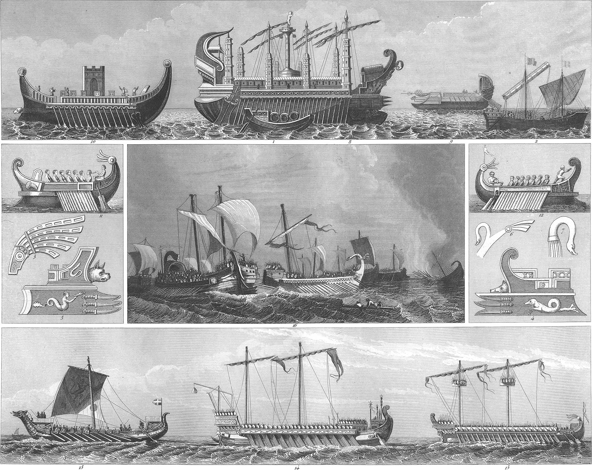
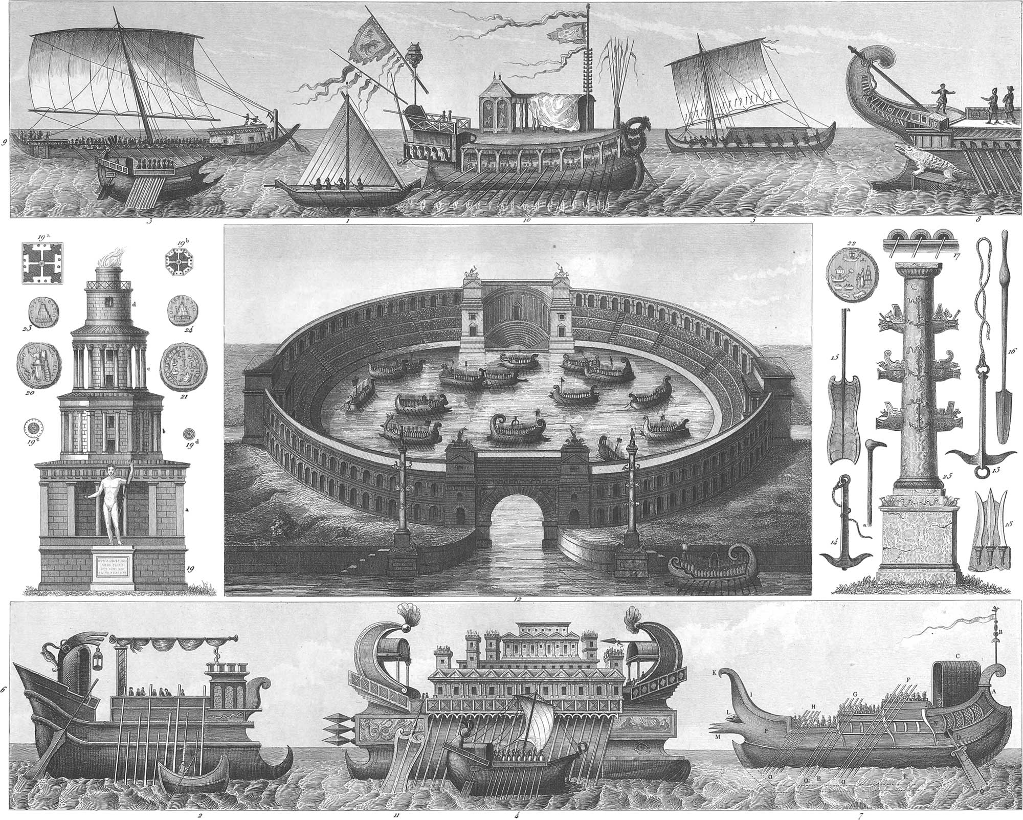
The most ancient boats, composed of a single piece of wood, appear to have resembled those now in use on the Tigris, Euphrates, and other rivers of the East. Pl. 2, fig. 2 is a Phoenician boat of that kind, to which we shall presently recur. In sea-going vessels, the hull was usually parallel with the surface of the water, the prow and stern, however, curving upwards. The hull was built on a keel, to which, as now, the curved or knee timbers were fastened. Along the side was a row of square holes, columbares (fig. 17), for the oars. The prow consisted of two parts: 1. A continuation of the keel (pl. 1, fig. 11; pl. 2, fig. 8), which served as a cutwater. Pl. 1, fig. 12, shows an ancient ship, after a drawing from Herculaneum. The flag-staff is at the stern. 2. The stem (rostrum, embolus), which at first was found only in ships of war, but afterwards in merchant vessels. Figs. 3 and 4 represent such rostra, which at first were nothing but strong beams covered in front with metallic plates, and serving the same purposes as battering rams in the military service. Afterwards the prow was constructed of planks hewn to a point, or with the metallic covering in the shape of a ram’s head. Finally, two or three points were used instead of one (figs. 9 and 14). Figs. 3 and 4, and pl. 2, fig. 18, show only the part of the prow above water. Pl. 1, fig. 10, gives the most simple form. As a defence against the prows of the enemy, stout beams projected from the ship, as in figs. 11 and 12. The stem was usually provided with one or two openings, called the ship’s eyes (fig. 11), through which the ropes were passed on landing. The poop was higher than the prow, and more richly adorned. In many ships there was here a kind of tent, from which the commander gave his orders to the crew (pl. 2, figs. 4, 6, and 7). This was sometimes placed at the prow.
Among the more ornamental parts was the aplustre, a piece of carved wood at the stern, usually in the form of a pendent bunch of feathers (fig. 6). The ship’s lantern was sometimes hung on this, or a small sail, to show the direction of the wind. Pl. 1, fig. 5, shows the most common form of the aplustre; but it was often found as in figs. 11 and 12. The possession of the aplustre decided the possession of the ship, and it was used as the signal of victory. If an aplustre was placed on the prow, it generally had the shape of a swan’s neck (figs. 6 and 7), though the form varied (figs. 1 and 2), and served to fasten the ropes on landing. The flaff-staff was at the stern, and bore the flag inscribed with the emblems of the ship (figs. 12 and 13, and pl. 2, figs. 7 and 10).
At the prow was the figure-head, the symbol from which the ship took its name. This was a boar’s head (pl. 1, figs. 3 and 4), a dog’s head (fig. 10), or some other image. The tutelar god was usually at the stern.
The vessel was propelled by oars (pl. 2, fig. 16), which were made of tough wood, in one piece, and plated with iron. The size of the vessel was determined by their number. The rudders or steering oars were shorter, but of greater breadth (pl. 2, fig. 15), and fitted into holes prepared for them in the sides of the ship (pl. 1, figs. 11 and 12, pl. 2, fig. 7). Sometimes the rudder was worked on the side (figs. 6 and 11). A handle (ansa) was generally attached to the upper end (pl. 1, figs. 11 and 12). The anchor originally had only one fluke (pl. 2, fig. 14a) attached to a heavy shank. It afterwards received the shape, fig. 14, and finally as in fig. 13, with a ring above for the cable, and one below for the buoy. The ancient anchors sometimes had three or four flukes. The masts of vessels were at first low, and made to lift out. There was usually but one in the middle of the ship (figs. 1 and 9), afterwards a second mast was rigged near the stem. The masts of war vessels were fitted up with a sort of basket containing slingers and archers (pl. 1, figs. 13). The ropes were of flax, hemp, palm-leaves, or papyrus; but the sails were of an inconvenient shape, and seldom more than one in a ship. They were both square and triangular, among the Romans generally triangular. At first they were constructed of rushes; afterwards they were woven, and colored black or red, as a token of mourning, victory, or the like. A second sail, usually triangular, was sometimes used at the prow, similar to the modern spritsail. The various forms and uses of the sails are shown in pls. 1 and 2.
The usual materials for ships were the wood of the pine and fir. The Egyptians and Phoenicians built them of cedar. Iron nails were at first used, then copper, and the seams were caulked with rushes, tow, and hemp, and paved over with wax or a compound of melted wax and rosin. The planks were put on in double thicknesses and covered with leaden plates.
2. Kinds of Ships. The ancients had:
- Row-vessels and sail-vessels. Merchantmen were usually sail-ships. Men-of-war used sails only on the voyage, but in action the ship was moved by oars.
- Covered and open vessels. Merchantmen had no deck, and when they used oars only one row of them; but ships of war had a deck, which was also the place for action. There were, however, some ships of war without a deck, and in that case they had only one bank of oars. The decked vessels often had two or three banks of oars, and as many decks one over the other.
- Long and round vessels. Merchantmen were usually oval, but men-of war were always longer. The long vessels were of different burdens; the lighter kind were always open, and were used by pirates.
We come now to a point which is not yet settled among the learned, namely, the banks of oars in a vessel. The old writers speak of ships with two, three, five, and even forty banks of oars, which they called biremes, triremes, quinqueremes, &c. The pictures in Pompeii and Herculaneum, the bas-reliefs on Trajan’s pillar, and other monuments represent these banks of oars on the outside, but not the interior arrangement of a ship. But we do not know how the sides could be high enough for so many banks; nor, if this were possible, how such long oars could be managed. It would take too much time to investigate this subject thoroughly here, but we are of opinion that the banks of oars were arranged one after another like, a ladder, corresponding with the representations that still remain. Pl. 1, fig. 13, shows a ship with three banks of oars (trireme). Fig. 14, a man-of-war with four banks (quadrireme). The rowers themselves were divided into three classes, upper, middle, and lower, and these sat regularly one above the other, the upper according to Thucydides receiving higher wages, because they used longer and heavier oars. An arrangement suggested by another writer is shown in pl. 2, fig. 7. According to this the different sets of rowers are placed at gradually ascending distances, the upper at F, the middle at G, and the lower at H.
Among the means of defence, besides the rostrum, we may enumerate:
- The breastwork, behind which the men protected themselves from the enemy’s archers and slingers (pl. 1, fig. 10).
- The tower. This was found only on the largest ships of war, and was occupied by archers, slingers, and engines for throwing missiles (fig. 10). These towers were made of wood. Some ships had eight of them. When it was desired to erect them of unusual height and strength two vessels were joined together.
- The baskets on the masts were found only in ships of war, rarely in merchantmen,
- The dolphin was used by the Greeks as an offensive weapon. It consisted of a heavy, brazen dolphin; suspended on a yard and thrown from above, it would beat in the enemy’s deck or sink his boats.
- The movable ram, similar to the military battering ram, and used against the enemy’s breastwork.
- The grappling irons were long rods with iron hooks, used in boarding the enemy’s vessel. Pl. 2, fig. 7, represents a Roman ship of war. A. The stern. B. The flag-staff. C. The commander’s seat. D. The rudder. E. The keel. F. The upper bank of rowers. G. The middle. H. The lower. I. The prow. K. The aplustre. L. The simple rostrum. M. The three-pointed rostrum. N. The breastwork. O. The oar. P. The ship’s eye.
Ships of war were manned partly with rowers and partly with fighting men. A quinquereme carried 120 fighting men and 300 rowers, of whom the last were generally slaves. They had no special places for sleeping, but lay in the open air, the rowers on their benches. The commanders shared all the hardships of the crew. The dress was a light tunic, and afterwards a woollen overcoat. The manœuvres of the ship were performed by the rowers, after the measure of a song, or the music of the flute and harp. Merchant ships always sailed in company, partly to guard against storms, partly against pirates. A well built ship sailed about one hundred miles in the twenty-four hours. Shipwrecks were so common that almost every third vessel was lost. Pilotage was in use among the Romans.
A large sum was expended by some of the ancient rulers for the building of show ships. Thus a ship was constructed by the orders of Hiero of Syracuse (264 b. c.) with flower gardens, canals, eight large towers, and an engine for throwing stones of 300 pounds’ weight and arrows twelve yards long. Archimedes was required to exert all his mechanical skill to float this vessel. Pl. 1, fig. 8, gives a representation of this ship, which was sent by Hiero to King Ptolemy II., as it was too large for every harbor but Alexandria. Ptolemy IV. had two ships built in the roads of Alexandria, one of which was 560 feet long, 76 feet broad, 96 feet high at the stem, and 112 at the stern. This ship was guided by four oars 60 feet in length. The upper bank of oars was 76 feet long, with melted lead in the handles as a counterpoise. Four thousand rowers were required to propel this vessel, which carried in addition 400 sailors and 2850 fighting men. Pl. 2, fig. 11, represents this ship. The other ship was 590 feet in length, 60 feet in breadth, and 80 in height, containing numerous sleeping rooms and banqueting halls, magnificently adorned with gold and ivory. A double gallery was extended along the outside. The show ship in which Queen Cleopatra (30 b. c.) visited Antony in Cilicia (pl. 2, fig. 10), had a gilded stern, oars inlaid with silver, and sails woven with purple. Delicious music accompanied the stroke of the oars, and a band of beautiful maidens clad as Graces stood at the rudder and managed the ropes. Cleopatra herself reposed on a splendid couch beneath a golden canopy, while she was fanned by boys who personated Cupid.
3. Marine Affairs of Different Nations. a. The Phœnicians. This nation, which first inhabited ancient Palestine, then the coasts of the Red Sea, and finally settled on the eastern coast of the Mediterranean, was the first that we find spoken of as addicted to navigation. About the year of the world 2560 the Phoenicians had colonies on almost all the islands of the Greek Archipelago, and 1250 years before Christ they made the first attempt to pass through the Straits of Gibraltar. Soon after they had colonies on the west coast of Spain, and it was the Phœnicians who changed the original coast navigation into the actual navigation of the sea, steering their course by the stars. Their polar star was not the same as that of the present day, according to Flamsteed and Bode being the star β in the shoulder of the Little Bear.
The Phœnician ships of war were sharp pointed at both ends, and moved by from 20 to 60 rowers. They were attended on their voyages by several transports. In general they bore the name of Argos. They had several banks of oars, sometimes amounting to twenty. The merchant vessels were round, the smallest of them being of very simple construction (fig. 2). Afterwards when their size was increased and they were used as transports they were made longer and more rounded at the ends (pl. 1, fig. 1). These were called liburnæ or three-oared gauli. The increased size of the vessels and the use of sails soon introduced an improved mode of ship-building, and the merchantmen took the form as in pl. 1, fig. 2. They were manned with from 12 to 24 sailors, and a suitable number of rowers. The sails were not used to the best advantage, for the art of trimming them to a side wind was not yet known. The voyages were accordingly very tedious when they did not fall in the time of the trade winds. In the days of King Solomon the Phoenicians were known as the most important sea-faring people, and no great maritime enterprise was undertaken without their aid. The rowers were seated in a large inclosure on the sides of the ship, from 15 to 20 on each side. This had the appearance of floating on the water. The masts were made to lift out; the sails were strengthened with rushes and the bark of trees; but the rigging was in the highest degree imperfect.
With the founding of Carthage (890 B. C.) the decline of Tyre commenced. This had been the principal state of the Phoenicians. The Carthaginians paid great attention to the improvement of navigation, and their fleet for the invasion of Sicily consisted of two hundred men-of-war and one thousand transports.
b. The Egyptians. Egypt, although the cradle of the arts and sciences, was at first far behind the Phœnicians in respect to navigation. This was, in part, owing to the religious ideas of the inhabitants. They had such a hatred of the sea, that the priests did not eat either salt or fish; and as a portion of the people were engaged in navigation, they were considered as a degraded caste. Another cause of the neglect of navigation was the want of ship-timber. The first navigation of the Egyptians was accordingly confined to rivers. They used only vessels made of the wood of the acanthus and tamarisk. Herodotus gives us the first account of Egyptian boats. They had a rudder at the stern, a mast of acanthus wood, and sails of papyrus (pl. 2, fig. 1). These Nile boats were in use in the time of the Romans. Some were made of wicker-work, covered with skins, and abound with painting and other embellishments. The importance of the river navigation may be inferred from the fact that the granite block which covered the altar in the temple of Latona, at Butus, measuring 240 cubic feet, was transported by water. The antipathy of the people to the sea was first overcome by Sesostris. He constructed a fleet of four hundred sail for the purpose of conquest; from that time the art of navigation made great progress in Egypt. Although the Egyptians in 1856 b. c. led a colony to Greece under Inachus in Phoenician vessels, in 1582 b. c. Cecrops sailed to Greece in Egyptian vessels, and there established the fortress Cecropia, afterwards Athens. The largest Egyptian ship of that day was built by the Phoenicians; this was a transport of fifty oars, which, 1475 b. c., brought Danaus to the coasts of Argolis, where he founded a colony. During the reign of Ptolemy, after the death of Alexander, who had delivered Egypt from the Persian dominion, a new era commenced for Egyptian navigation. The first enterprise of this kind undertaken by Ptolemy Lagus was the enlargement of the harbor of Alexandria, by connecting the island of Pharos with the main land by a dike. Here he placed the first light-house, as a beacon for ships; this stood on the eastern point of the island, and was completed by Ptolemy Philadelphus: it consisted of four stories; it was built of white marble, and was surrounded with galleries resting on pillars; the total height of this building was four hundred feet; the lower story formed a square, of which each side was over one thousand feet in breadth. Pl. 2, fig. 19, gives a view of the light-house, and figs. 19a, 19b, show the ground plan of the different stories. Under the Ptolemies, also, the two large ships of which we have already spoken, were built. But however great the eminence which Egypt at first attained under this dynasty, it afterwards sank to an equally low depth; and when under Ptolemy XII., Julius Cæsar burned an Egyptian fleet of 110 sail, on the open sea, and sacked Alexandria and Cairo, the Egyptian marine, which had flourished for two thousand years, was left almost without a trace on the records of history.
c. The Greeks. The Phoenicians, whose navigation was more than four hundred years old at that time, brought a colony to Greece under Inachus in the year 1856 b. c.; but when, three hundred years later, the colony under Cecrops arrived thither, the people were found in a savage state, living in caves, and suffering under the yoke of the pirates. The first thing necessary, therefore, was to establish navigation, in order to act against these enemies. Connected with this were certain relations of trade, which was still in such a rude condition that as late as seven hundred years after Abraham only barter was known in Greece. The inhabitants on the southwest coast of Attica were the first who engaged in navigation, and the most ancient voyage authenticated by history was the Argonautic expedition to Colchis, for which Jason, probably 1200 b. c., constructed a vessel of a much larger size than had hitherto been known in Greece. After the Argonautic expedition, the Greeks engaged more extensively in navigation. In eighty years the siege of Troy took place, with a fleet of 1,186 ships; the largest carrying 120, and the smallest 50 men. The first ships of the Greeks seem to have had no keels; Homer makes no allusion to any, and all the Greek vessels of that age were large barques, with a single bank of oars, as shown in pl. 2, fig. 3. They were usually round, and the stem and stern were so elevated that the ship almost looked like the moon in the last quarter; afterwards the stern only was raised so high (fig. 4). The Platæans introduced the use of two steering-oars. The oldest vessels, which were entirely open, were called aphracti; the round half-decked ships were called kataphracti. They had willow guards at the side to break the force of the waves; only one mast was used, which could be taken out at pleasure; the mast bore one or more sails, which were moved by ropes. These at first were made of bark, but afterwards of skins; four such ropes at the prow and the stern held the mast. The ships were often painted in encaustic with lively colors, which helped to preserve them.
The Greek trading vessels had a wide bottom; their length was only three times their breadth, while the ships of war, on the contrary, were long and pointed, with usually not more than twenty rowers on a bench, the Greeks being skilful in the use of sails on the high seas. The ships were drawn ashore to winter, and were often conveyed considerable distances by land. The merchantmen generally had two banks of oars; some had two banks at the stern, and only one at the prow, the prow being made narrower on that account. In the time of the Apostles very long vessels were in use, with two decks at the stern; there was also a midship-deck, with a room for offering sacrifices. At the end of the bowsprit, in the forward part of the ship, was a short mast with a sail, behind which ran a small gallery, from which the orders were given to the crew. The Greek ships were adapted for sails as well as oars; they were usually triremes, as in fig. 6, although there were sail-vessels with one bank of oars (fig. 4). These galliots were afterwards less curved, longer, and with two banks, of oars (fig. 5).
The first ships were no doubt constructed without keel-beams, but these were used at a later period. The ship’s bottom was fastened to the beam on both sides with strong planks; this was the place for the ballast; next to this was the hold, which was divided off by the timber knees attached to the keel. The oar benches were on each side, the oars passing through openings in the ship; above the oar-benches was a gallery for passengers. The prow, the stern, and the sides were often richly ornamented with carved work; the stern was rounder than the prow, was built higher, and was fitted up with an arched canopy, under which sat the steersman. The steering-oar was at the stern; the larger class of ships had two, which passed out of a kind of square box at the sides, in which was a round hole. Rudders similar to those now in use were not known until a later period. The mainsail was attached to the mast; a sail at the stern often served to increase the speed, and a smaller one was sometimes raised at the prow; a topsail was in use at the time of the Apostles. If the vessel had more than one mast, the mainmast was amidships. Besides the usual ships of war, the Greeks had vessels for transporting horses, and others for reconnoitring, whose breadth was only one ninth of their length; these carried few men, but were of great speed. There were boats of different sizes, which communicated between the vessels of a fleet. The largest Greek ship was that which the city of Heraclea sent to the aid of King Ptolemy Ceraunos; this had 800 oars and 1,200 marines.
d. The Romans. The Romans were confined for a long time to a rude coasting navigation, which scarcely extended beyond the neighboring island of Sicily; even their first larger voyages were performed in hired vessels, until after the first Punic war. At that time they suddenly resolved to create a fleet of their own, and they accomplished this with incredible rapidity: within two months they built a fleet of 120 vessels, with which Caius Duilius risked an engagement, and came off victorious. This victory was celebrated by the erection of a monumental column in the forum at Rome (pl. 2, fig. 25), which was ornamented with the beaks of the conquered vessels. Similar monuments succeeded this columna rostrata, which was erected a. u. c. 494, although the Romans obtained no other victory so signal.
The Roman ships must evidently have been built on the Greek and Phœnician models. The merchantmen were mostly sailing vessels; the ships of war had both sails and oars: and we again meet with the Greek biremes, triremes, and so forth. The largest and most usual men-of-war were quinqueremes, but there were also light vessels with a bank on each side, which were often employed for reconnoitring; smaller vessels, called cymbæ, were used for quick transportation. The vessels of war were manned with rowers and marines, Roman citizens of the lower class. A quinquereme counted four hundred rowers. The sea-captain directed the affairs of the ship, but the soldiers had their own commander. The admiral’s ship was designated in the day by a flag, and in the night by lanterns. Pl. 1, figs. 11 and 12, represent smaller Roman triremes, as they are found on the bas-relief of Trajan’s pillar. Fig. 13 is a large trireme, fig. 14, a quadrireme. The principal difference between the ships of the Romans and those of the Greeks and Phoenicians consisted in the greater length of the former, which admitted two masts in the larger vessels. The masts were usually provided with baskets, containing slingers and archers.
Before leaving the subject of ancient navigation, we must briefly describe the method of naval warfare, and of manœuvring ships at sea. The crew were summoned on board by a signal from the trumpet. First came the rowers, and then the marines; the crew of the transports came last. Before sailing, sacrifices were offered, and also after returning from the voyage. During an engagement, no use was made of the sails, and the ship was moved only by the oars. In the order of battle, the largest ships took the centre, the light ships took the wings, and others formed a reserve. The ships were generally drawn up in the form of a half- moon, but sometimes in that of a wedge or circle. The admiral sailed through the fleet in a light vessel, exhorting the men to courage. The sails were then furled, and everything made ready for action, for which the signal was given by a red flag from the admiral’s ship. The signal for attack was then sounded on the trumpet, the ships were driven against each other, the slingers and archers took deadly aim at the crew of the enemy, and the rowers endeavored to destroy the opposing vessels with the beaks of their own. If this did not succeed, grappling irons were thrown out, the vessels were drawn together, and the action became a personal conflict. It was often attempted to fire the enemy’s ships, either by fire-ships or by throwing earthen vessels filled with burning pitch and sulphur. Pl. 1, fig. 16, represents a sea fight. The victorious ships returned home, adorned with flowers and laurels.
The warlike spirit of the Romans was cherished in their games and amusements. Sea fights were exhibited in time of peace, and were called Naumachia. These were introduced by Julius Cæsar. The circus was so arranged by Maximus that it could be filled with water to a considerable depth. Ships were built on the arena, the water let in, and a regular battle fought by slaves and prisoners, by whom the vessels were manned. These mock engagements often resulted in dreadful slaughter on both sides. At a later period, they were fought on the larger lakes, or artificial lakes were prepared for their representation. An amphitheatre for this purpose was erected by Domitian, of which pl. 2, fig. 12, gives a sketch. This structure was elliptical, 1300 feet long, 200 feet broad, and had room for the manœuvres of 30 triremes and a great number of smaller vessels. The avenues to the building were richly ornamented; the arena was placed under water by means of subterranean canals, so that it could be quickly dried for the exhibition of the gladiatorial contests. The last spectacle of this kind was given by Aurelian in honor of the victory over Queen Zenobia.
Navigation of the Middle Ages
During the period which we call the Middle Ages, that is, from the fall of the Western Empire and the succeeding centuries, the results of navigation were very insignificant, since it shared in the general depression of science and art at that time. The most important naval enterprise was the expedition of Belisarius against the Vandals in 533, with a fleet of 500 sail, 15,000 warriors, and 20,000 sailors. Triremes had then gone out of use, and there was no convoy for the army but 92 light brigan tines, which could not resist a serious attack.
1. Anglo-Saxons, Normans, and English. Meantime, the northern nations of Europe appear on the theatre of history, and the first maritime expedition of which we have any account was the voyage of the Anglo-Saxons to Britain under Hengist and Horsa, a.d. 449. This was performed in light, frail vessels, with keels of light timber, and sides of wicker-work, laid over with skins. The vessels in which the Normans undertook their piratical expeditions in the seventh century were of little better construction. The Grecian and Imperial navy at that time consisted of galleys with two banks of twenty-five oars on each side, making one hundred oars in the whole.
From the ninth century, England was the most important maritime nation. Alfred the Great, who was in conflict with the Normans and Danes, effected such great improvements in her navigation, that in the year 897 her ships were without an equal in any nation. They were built as galleys, with from forty to sixty rowers on each side, while William of Normandy, in his expedition against England in 1066, which, after the battle of Hastings, gave him the name of Conqueror, used only vessels (pl. 1, fig. 15) of such diminutive size, that they could carry no more than twenty armed men besides the rowers.
A great impulse was given to navigation in the middle ages by the crusades, and the frequent wars of the English, French, and Spanish. In the battle of Sluys, 1339, the French fleet consisted of 400 vessels, among which were 120 large ships. The number of men who fell in this battle is variously stated from 10,000 to 30,000, from which we may infer the magnitude of the ships engaged. The construction of vessels at that period is shown from the remains of tapestry, and from pictures in ancient manuscripts. The English ships were not so long as those of the Normans. The stem and stern were quite sharp, beak-like, and of equal height. They were ornamented with dragons’ heads, and the stern often had two projections in the shape of wings. The steering oar was managed at the side. The mast was amidships, and the rowers worked standing. The anchor was very large, with a stock. The Norman vessels were sharper and higher in the prow than in the stern. The steering oar was of the Greek fashion, with a handle. The mast stood more towards the prow, and bore sails and a flag with the Norman arms. The war barques from the year 1377 were almost round, with a regular keel. They had a kind of wall or breastwork fore and aft, the sails were stitched, and the mast, stayed by a rope, stood amidships. A war ship of the same time was high in the sides, rather short and round, with a quarter-deck forward; a rudder, similar to the modern rudder, at the stern; the mast with shrouds and a basket. The galleys had a similar construction, but were less round forward; they had no mast, but houses on each side for the rowers. At the stern was a kind of tent. The war ships had seldom more than one mast. This consisted of a single piece; the square sails were attached above to a yard, which, when the sail was not used, was let down to the deck. The planks of the ships lapped over each other like a weather-boarding, and were not caulked.
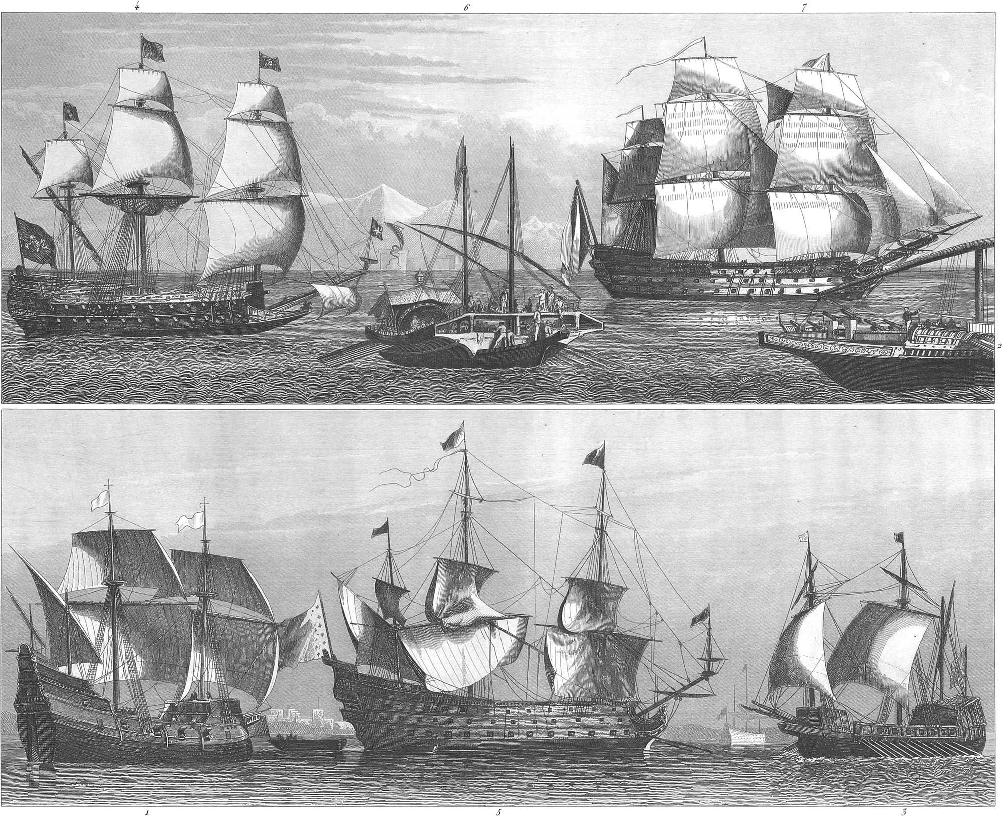
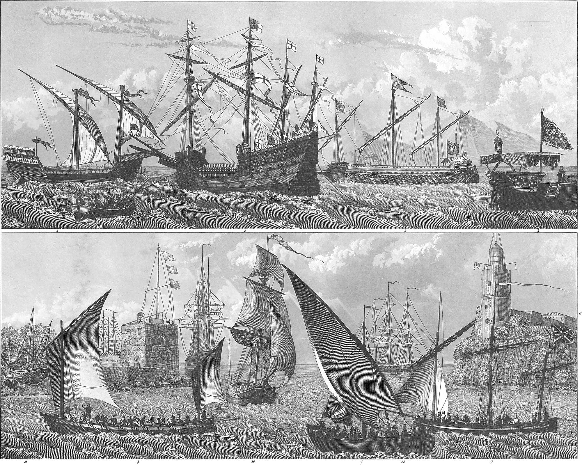
Under Henry VIII. of England, navigation assumed a new form, and during his reign (1485–1509) the permanent English marine was founded. We have representations of the ships constructed at that time. They carried cannon, for which Deschanges of Brest invented port-holes in the year 1500. One of these vessels was called The Harry Grace à Dieu, or The Great Harry (pl. 4, fig. 2). The quarter-deck, which we have already mentioned, here formed a regular deck and forecastle, bearing two batteries, one over the other, the lower consisting of 5-pounders, the upper of 4-pounders and 2-pounders. The lower side batteries had culverins (18-pounders), and the upper, demi-culverins (9-pounders). All had portholes, but the guns in the forecastle were discharged from round ship’s-eyes, and had no side bearing. Aft, near the rudder, were 24-pounders or 32-pounders, to fire on the enemy during a retreat. The ship had four masts, or with the bowsprit, five, all of which were in one piece; they had two baskets and double topsails. The rigging was very simple. The ship was of 1000 tons burden, and carried 120 cannon. The carac built by Francis I. was of the same magnitude, and had 100 cannon. The Sovereign of the Seas, built by James I. (pl. 3, fig. 4), shows the first artificial lengthening of the mast by the addition of a topmast. This vessel was 128 feet long, 48 feet broad, and carried 106 heavy cannon. The construction of this ship resembles that of the present day; the misshapen high castles have disappeared, although the sharp projection of the prow reminds us of the beak of the ancient ships; the sails have increased in number; the rigging is more artificial; and the position of the masts is favorable to rapid and secure sailing. The sail under the bowsprit is worthy of notice. This was first used on The Harry Grace à Dieu, and was the origin of the present jib.
2. Spaniards and Portuguese. The Spanish marine was of a good deal of consequence at that time. The Spaniards built fog their great voyages of discovery a number of galleys, with six or seven decks, and from 1800 to 2000 tons burden. The Portuguese built for the East India trade large galleys called caracs (pl. 4, fig. 1) which were moved by sails and oars, and instead of a rudder at the stern had two large oars with broad blades. The rowers sat on cross-pieces, looking to the outside, sometimes with a row of twelve men on each side. The great Spanish Armada, which sailed to England under the Duke of Medina Sidonia in 1588, consisted principally of ships of war, as represented in pl. 3, fig. 3, few of which carried over 30 guns, and which were for the most part moved both by sails and oars. The number of regular ships of war was 24; there was one large galley from Naples, and four Portuguese galleys, which were manned with 2088 galley slaves for the oars and 900 marines. In addition to these two fleets, the Armada had eight separate squadrons, amounting in the whole to 59,120 tons burden, and carrying 2765 guns. They were manned with 7865 sailors and 20,671 marines, while the English fleet was composed of only 181 vessels, of which only 34 could be regarded as ships of war, the remainder having no vessel over 200 tons. The whole fleet amounted to 31,985 tons, with 17,472 men. The Spanish fleet, in which with the rest of the company were 669 monks and a number of women, set sail May 29, 1588. The admiral’s ship had a castle with towers; all the masts were wound with thick ropes, to break the force of a cannon ball; and the sides of the ship were so solid that no ball could pierce through them. Of this powerful fleet, not a ship reached England. During a calm night, the English commander sent eight fire-ships into the midst of the fleet, joined battle in the morning, and in a few hours gained a decided victory. The retreating Spanish fleet became a prey to the winds and waves, so that only 53 ships succeeded in reaching Spain in a most distressed condition. The Spanish navy has never since attained so high a point. The Portuguese marine, which in the 16th and 17th centuries formed an important mercantile fleet, is now insignificant.
3. Genoese and Venetians. The naval power of the Genoese and Venetians was of great importance in the middle ages. In the year 1100 the Genoese placed ships of war at the service of King Baldwin of Jerusalem; but in the succeeding centuries the marine gradually declined, until it became wholly insignificant, when Genoa was reduced to the dominion of France and afterwards of Milan. In the ninth century Venice was in possession of the whole coasting trade of the Adriatic Sea, which it secured by a navy of considerable magnitude. In the struggle for Pope Alexander III., 30 Venetian galleys fought against 75 galleys of the Emperor Frederick, and gained the victory under the Doge Sebastiano Ziani, in 1177. From that time date the so called supremacy and marriage of the Doge with the Adriatic Sea and the famous voyage in the Bucentaur. At the end of the fourteenth century, Venice possessed a fleet of 3000 merchantmen, of which 300 were of 700 tons burden. The fleet was manned with about 25,000 sailors, protected by 45 galleys with 11,000 marines. In the fifteenth century, the naval arsenal at Venice employed 16,000 laborers, and had 36,000 seamen. A kind of vessel which came into general use at that time, and which properly forms the transition from the triremes of antiquity to the ships of modern times, was the galley. This was usually from 130 to 140 feet long, and from 16 to 20 broad. Pl. 3, fig. 6, gives a front view of this vessel. They were somewhat smaller than the galleys constructed by Badoaro in the year 1560. In the thirteenth century, galleys were the only vessels of war employed on the Mediterranean; in the fourteenth century they were divided into three classes, and in the sixteenth century appear to have passed beyond the Mediterranean; but in the middle of the seventeenth century they went out of general use, being now employed only as coasting vessels. The galleys had twenty-five oars on each side, which were moved together by beams moving with them. The benches, on which five men sat for every oar, were built on the outside of the vessel. A passage ran through the middle of the galley, which served for the protection of the cargo and the quarters of the men, and through which the captain passed back and forth. The whole was protected from the rays of the sun by a sort of tent. Five guns usually stood on the prow (pl. 3, fig. 2), and on the side, several swivels and swans’-necks. At the stern (pl. 4, fig. 3) were the emblem and name of the galley, with the captain’s state-room, and usually several six-pounders. The galleys carried two masts of moderate height with triangular sails, the largest of which was unfurled only in a light wind. There was sometimes also a small mizen-mast. The principal galley was called the reale; the next, the patron or captain. Small galleys of from sixteen to twenty oars were called demi-galleys, and those with broad sterns bastards. The convoys had a complete military organization, the commander holding a council of war with the captain and officers of the galleys. The most exact directions were given with regard to lading and manning the vessels. Thus, for example, the vessels of the convoy destined to Flanders must be manned with 200 free seamen, among whom were 180 rowers and 12 archers. The freight must not exceed 140 tons, 60 tons being articles of merchandise. At times of pressing danger, 30 archers were taken instead of 12. Since Venice has belonged to the Lombardo-Venetian kingdom, and with that to Austria, her marine has been absorbed in the Austrian.
4. Scandinavians and Russians. The northern nations of Europe, especially the Scandinavians, were skilful navigators as early as the fourth century. In the sixth century we have accounts of the sea-kings (Vikings), who dwelt on the headlands and followed piracy. In the year 872, Ingulf and Hjörleif and several other noble Normans fled from the tyranny of King Harold Harfagger to Iceland, which was then almost uninhabited, but in 925 the population amounted to 80,000, who lived in a well organized state and gained their support partly by commerce and partly by piracy. The discovery of America has been ascribed to them by Danish antiquarians, with a show of proof found in some alleged Runic inscriptions on ancient monumental stones in Rhode Island and Connecticut, but their arguments seem to be destitute of all historical validity.
5. Netherlanders. The navigation of the Netherlands was of great importance in the middle ages. Their various commercial relations demanded a large mercantile marine, together with a powerful navy for its protection. The Dutch marine, accordingly, during a part of the seventeenth century was the largest in Europe. Hence great attention was paid to the art of ship-building. In consequence the Dutch ships were of a superior character, and some of the best specimens of naval architecture are of Dutch origin. We shall describe their peculiarities in another place. We find in the early naval registers of Holland ships of 90, 92, and 94 guns, but we are struck with their comparatively small number of men. The admiral’s ship Unie of 94 guns had only 550 men; the rear admiral’s ship Zeeland of 90 guns only 425 men; and the ship of the line Westfriesland of 88 guns only 470 men. In the war between Holland and France and between Spain and France, in which Holland lent her aid to Spain, Holland had 70 ships of the line and 30 frigates in active service. Among them were 14 ships of from 84 to 94 guns, 17 of from 68 to 76 guns, 19 of from 60 to 54 guns, the remainder with 54 guns, and the frigates with from 30 to 40 guns. In this war the Dutch admirals Van Tromp and De Ruyter gained immortal renown. A peculiar branch of the Dutch navigation was the herring fishery, for which this country in the middle ages had almost a monopoly. The Dutch first engaged in this fishery in the latter part of the 13th century, Edward III. of England having given them permission in 1295 to take herring on the English coast. Wilhelm Beukelszoon brought the art of pickling herring to perfection in 1397. In 1644, Holland equipped 1054 herring smacks. These were round both in the stem and stern; they had only one mast and one large sail, except a triangular stay-sail and another light sail on a small mizen-mast. They carried from 350 to 500 barrels of herrings. They were manned by about fifteen sailors. The Dutch also engaged in the whale fishery and fitted out voyages to Greenland. The Greenland Company, established in 1614, however, had such ill-success that they surrendered their charter in 1651.
6. The French. France also assumed an important place among sea-faring nations in the middle ages. Her marine was derived directly from the Greeks, for Massilia, now Marseilles, was a Greek colony and a powerful rival of Carthage. Marseilles was most distinguished in the time of the crusades. It was her vessels that bore the crusaders and pilgrims to Palestine. The business was reduced to a perfect system. On an average, from 6000 to 7000 pilgrims were carried annually. The master of the vessel bound himself by an oath to care for the pilgrims, whether sick or well, alive or dead. Each pilgrim was guaranteed a space for sleeping six feet wide, seven feet long, and twenty inches high. Every ship was obliged to be armed, and with a sufficient force to repel the attacks of an enemy. Another landing-place was Aigues Mortes, which, now several miles from the sea, at that time had a good harbor. For a long time navigation made little progress on the north-west coast of France. In 1513 a commercial marine of some importance was established at the port of Harfleur. Pl. 4, fig. 4, shows the arrangement of the oars and sails in the galleys during the reign of King Francis I. The construction of ships of war improved with the improvements of the merchant vessels, and (as shown in pl. 3, fig. 1) they received a more convenient, symmetrical, and elegant form. But the French navy was raised to a formidable degree of power under Colbert, the celebrated minister of Louis XIV., and at the battle of the Hague, May 31, 1692, it had a decided supremacy over the maritime force of every other nation. At the commencement of that year, it numbered not less than 101 ships of the line, 8 of which carried from 100 to 108 guns, and all of them remarkably well manned. The Soleil Royal (pl. 3, fig. 5), of 108 guns, had 1000 men; the Foudroyant, of 110 guns, had 900 men; and the Merveilleux had 850 men. The number of frigates, bomb-ships, and so forth, corresponded with that of the ships of the line. In order to keep the fleet in constant action, Louis XIV. kept up an almost uninterrupted naval warfare with Algiers, Tunis and Tripoli, Genoa, and so forth. The harbors of Toulon and Brest were placed in the most excellent condition at a great expense, and a new harbor formed at Rochefort. Dunkirk and Havre de Grace were also at that time important naval ports. The sea-service then employed 60,000 men, but the commercial marine in 1664 numbered only 2368 vessels, of which only 19 were of from 300 to 400 tons burden. In the year 1843, France had 15,025 merchantmen, amounting to 647,107 tons. As a contrast to the Soleil Royal, we have represented (fig. 7) the ship of the line Ocean, carrying 108 guns, built under Louis XVI.
7. The Germans. The German navy, small as it now is, held an important position in the middle ages, although the geographical situation of Germany, whose coasts are washed only by inland seas, seems to assign it only a subordinate place.
In the ninth and tenth centuries the German trade was mostly domestic, although the Rhinelanders pursued some traffic with the Scandinavians and with England. Dragawitt was a commercial port in Holstein in the year 789. Rorich was a celebrated trading city at that time on the site of the modern Rostock, and was afterwards destroyed by the Danes. Lethira, which was destroyed by Otto I., was the modern Stargard. Lübeck was built by King Wilzen Liuby, destroyed in 1139 by the Russians, and rebuilt in 1144 by Adolphus II. of Holstein-Schaumburg, at a little distance from its former location. In 830 Stettin was also a place of considerable commerce, and Vineta, on the island of Usedom, in the ninth century was one of the largest cities of Europe, maintaining mercantile relations with Greece, Asia Minor, Tartary, China, and India. The harbor could coatain 300 ships. In the eleventh century the city was buried in the sea by a sinking of the earth, but in the sixteenth century the ruins of buildings and towers could be seen at low water.
German commerce received a powerful impulse at the time of the crusades, and this circumstance, together with the piracies that were committed by the inhabitants of the coast on the North Sea, exerted an important influence on the development of navigation. At that time, especially while the Emperor Henry IV. was under the Papal ban, the administration of justice had almost entirely ceased, and the cities leagued together for mutual protection. The first of these alliances was the league of the Rhenish cities, of which Cologne was the centre. This was followed by the Suabian league, which was important in relation to the navigation of the Danube and the trade with the Levant, and afterwards by the Hanseatic league, which embraced North Germany, including the territory conquered from the Vandals east of the Elbe and Oder. At first this league included only 14 cities, but in the 14th century the number had increased to 77. After the Hanseatic league had exerted a favorable influence for a full century, its supremacy was shaken and its privileged trade with foreign countries destroyed by the increase of trade in the interior of Germany, and the growing power and industry of the States, in which it had its last depositories. Finally, even its name disappeared from history, and at this time the title of Hanseatic cities is borne only by Hamburgh, Lübeck, and Bremen.
The commercial confederation of the Hanse had the natural consequence of improving the navigation of Germany. In the eleventh century a fleet sailed from Cologne to England; in 1247, 300 ships were equipped for the crusades at Cologne; and Lübeck at the close of the thirteenth century was the mistress of the Northern seas. Her fleet fought the battle of Travemunde with the Danish King Waldemar II. in 1235, which terminated in the total defeat of the Danes. The Hanse towns conquered Copenhagen four times, and in the year 1248 despatched their fleet of 280 ships, with 12,800 men, against King Erich VII. of Denmark. During the period from 1563 to 1570 they sent 19 ships to the aid of Frederick II. of Denmark against Erich XIV. of Sweden.
Navigation of Modern Times
We shall describe the characteristics of modern navigation in the technical portion of this work. At present, before closing our historical survey, we will give a brief view of the navies of different powers and their condition within the last few years.
The Russian Navy, according to recent official returns, consists of 56 ships of the line, with from 74 to 120 guns each; 48 frigates, with from 40 to 60 guns, and a proportional number of corvettes, cutters, and steamers.
The Swedish Navy is composed of 21 ships of the line, of which only ten are in commission; 8 frigates, 8 corvettes and cutters, 2 steamers, and 247 gunboats. The last form the guard-fleet for the harbors. Norway has only a coasting-fleet of 117 gunboats.
The Naval Force of Great Britain, according to an official document presented to the United States in 1846, by Mr. Bancroft, the Secretary of the Navy, consisted of vessels in commission, as follows: 17 ships of the line, with 1570 guns; 32 frigates, with 1146 guns; 71 sloops, brigs, and bombs, with 856 guns; 33 schooners, cutters, tenders, and ketches, with 66 guns; 6 steam frigates, with 60 guns; 54 steam sloops, with 270 guns; 21 steam packets, with 42 guns; 9 other steamers, with 18 guns; 5 transport and troop ships, with 70 guns; 84 receiving ships, coast-guards, and other non-effective vessels, with 485 guns, making a total of 332 vessels and 4538 guns. At that time 100 vessels of war were on the stocks, intended for 3161 guns; and 204 vessels were in ordinary, with 9933 guns. During the Continental war, the seamen in the British service amounted to 140,000; there were 20,000 to 30,000 marines; 160 ships of the line, and 150 frigates, but before the close of the war the force was considerably reduced. In 1815 a still further reduction was effected by Parliament; and in 1817 the number of seamen was reduced to 13,000 and of marines to 6,000. An increase was subsequently ordered, and in 1831 there were 22,000 seamen and 10,000 marines. The pay of this force, at £2 12s. a month, amounted to £1,081,000 sterling; and their support, at £1 9s. a month, cost £603,000. This added to the expense of magazines, improvements, and so forth, makes the annual sum of two million pounds sterling, without reckoning the outlay for pensions and half-pay, or for building, repairs, and construction of harbors, so that the annual charges for the navy are not less than four and a half millions. The commercial navy of England in 1843 consisted of 24,500 vessels and 160,000 seamen, with an aggregate value computed at twenty-six and a half millions sterling.
The Dutch Navy consists of 15 ships of the line, of from 54 to 84 guns; 20 frigates, 21 corvettes, and 26 other vessels of war. It has in addition 13 steamships, of 7 to 8 guns each, and 165 gunboats. The colonial marine in India, in 1845, was composed of 21 vessels, including one frigate of 48 guns, and two iron steamers of 11 guns.
The Danish Navy contains 6 ships of the line, with from 66 to 84 guns; 8 frigates, of from 40 to 48 guns; 4 corvettes, of from 20 to 26 guns; 1 barque, of 14 guns; 5 brigs, of 12–16 guns; 3 schooners, of 6 guns; 3 cutters, with six guns and 2 falconets; 23 bomb-sloops; 17 bomb-gunboats; 139 common gunboats, 1 steamship of 200 horse-power, with 2 sixty pound mortars and 6 24-pounders; and 1 steamship of 80 horse-power, with 218-pounder swivel guns.
The German Navy, established in 1848, as yet only contains 5 frigates, 3 of which are steamers; 6 steam corvettes; and 26 gunboats; and there is hardly any chance of its increase, or even maintenance, if the people do not realize the combination of the many small and weak German states into one single state, or a confederation with a central government, as the only executive for foreign affairs.
The French Navy consists of 25 ships of the line, 37 frigates, 30 corvettes, 44 brigs, 43 small armed vessels, and 32 transports. Of steam vessels, it has 1 ship of the line, with 80 guns, of 960 horse-power; 20 frigates, of from 450 to 650 horse-power; 27 corvettes, of from 220 to 450 horse-power; and 57 smaller steamers of different powers.
The Portuguese Navy numbers 40 vessels, with 940 guns, including 2 ships of the line, with 80 guns; 6 frigates; 8 corvettes; 1 steamship, and so forth.
The Spanish Navy is now greatly reduced. Of 2 ships of the line, 4 frigates, and 18 smaller vessels, which were in commission in 1834, the greater part are unfit for service, and most of the naval officers are old and worn out. The naval departments are discontinued, the General Marine Office only existing at Cadiz. In 1802 Spain had 68 ships of the line and 40 frigates.
The Sardinian Navy has 5 frigates, with 60 guns; 2 corvettes, 6 smaller vessels, 12 gunboats, and 1 steamship.
Tuscany has a small navy of 3 schooners and 2 gunboats. The navy of the Pope consists of 2 frigates and 4 smaller vessels.
The Neapolitan Navy numbers 12 vessels, including 1 ship of the line, with 84 guns; 3 frigates, and 4 corvettes.
The Austrian Navy has 8 ships of the line, 8 frigates, 4 corvettes, 6 cutters, 7 schooners, and several steamers and smaller vessels.
The Turkish Navy consists of 10 ships of the line in commission and 5 not in commission; 15 frigates, 3 steamships, and several corvettes and other vessels.
The Egyptian Navy at present has not more than 3 ships of the line, 1 frigate, 1 corvette, and 2 cutters.
The Navy of the United States consists of 11 ships of the line, with 860 guns; 1 razee, of 54 guns; 12 first class frigates, with 528 guns; 2 second class frigates, with 72 guns; 22 sloops of war, with 418 guns; 4 brigs, with 40 guns; 5 schooners, 15 steamers, and 5 storeships and brigs.
The Brazilian Navy has 90 vessels, including 1 ship of the line, 3 frigates, and 4 corvettes.
Navigation of Non-European Nations
With the exception of the civilized portion of the American continent, navigation out of Europe is in a low degree of advancement, corresponding with the general want of culture of those nations, and the recent period at which they have come in contact with Europe. Like every branch of human knowledge, navigation has been neglected by those nations whose geographical position has isolated them from mutual intercourse with cultivated nations. A more intimate commerce with Europe is followed by the introduction of European navigation, so that a strictly national marine has no chance of existence.
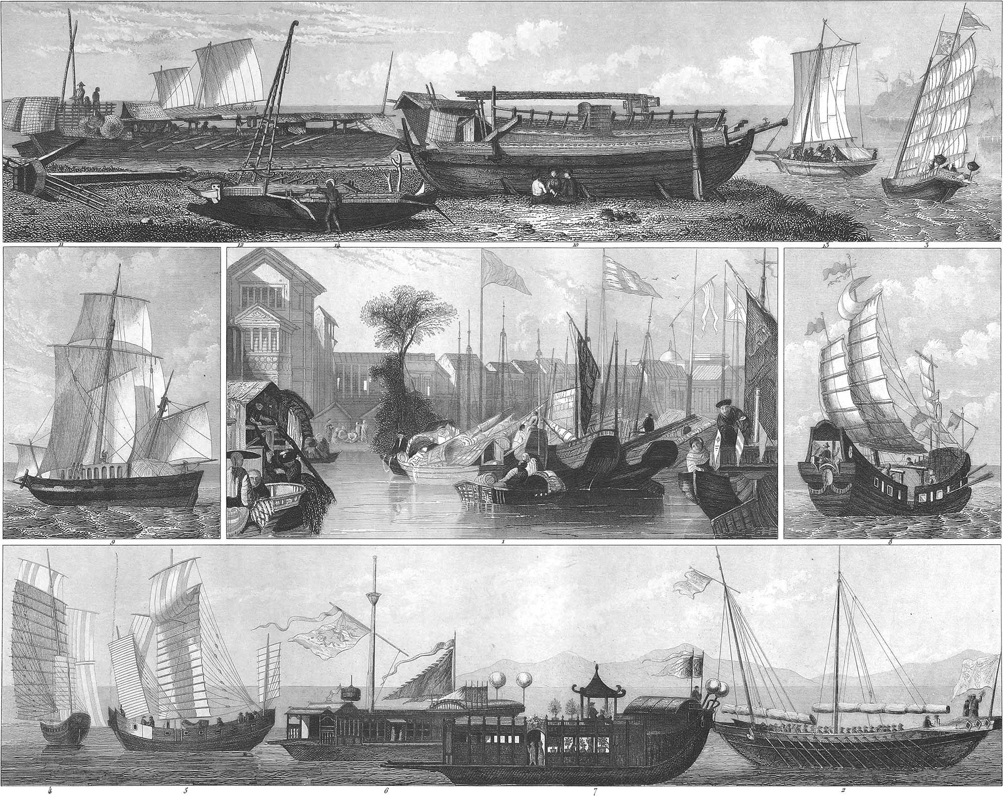
Among the nations out of Europe the Asiatics and Africans have always shared to a certain degree in European cultivation, and hence the art of navigation has made some progress among them, although the influence of the European marine predominates. The only exception to this is found in China. The Chinese, a people in many respects so enigmatical and mysterious, have marked out their own path of cultivation, in which for many thousand years they have attained a degree of refinement, of which we have scarcely a conception. For an incredible period they have possessed most modern inventions, but the Chinese wall which has concealed from us their progress, has also until within a few years shut them out from European civilization, so that they have remained in the same position which they have occupied for centuries. But the extensive marine of China is so far behind the European, that the Chinese junk Kay-Ying, which was lately purchased by the English and taken to London, was the first ship which had ever ventured beyond the track of their wide coasting navigation, a Chinese voyage round the Cape of Good Hope being an extraordinary occurrence.
1. Africa. Until the seventh century this portion of the world was almost wholly unknown, and as regards the principal part of its interior is still in the same condition. The first descriptions of this interesting country are given by Herodotus. The region bordering on the Red Sea and the Persian Gulf, and the coast of the Mediterranean, has no special interest in connexion with our subject, since its navigation has become entirely absorbed in the European. We shall accordingly confine ourselves to the east and west coasts of Africa.
The fishing-boats of Mocha, in the Straits of Babelmandel, are about 24 feet long, with 16 feet in the keel, forming a long and pointed oval; the mast is scarcely 12 feet high; the sail is nearly square, and the oars are of great length, with pear-shaped paddles two feet wide. The fishing-boats in the bay of Maskate are of a very different construction. They have a flat bottom, with so slight a curve, that its outline is nearly in the form of a trapezium. They have no knee-timbers, and their planks are bent by fire, lapping over each other, and fastened to the floor with bands and clamps, forming a kind of seam. At the stern there is a rudder, reaching two feet under the bottom of the vessel, and managed with two ropes. The mast is 20 feet high, and carries a square sail on the yard. The freight boats are rounder, being five feet high in the sides, and the planks consist of several different pieces; the bottom rises pretty sharp both at stem and stern; the rudder does not pass below the bottom of the vessel, and is moved with a small bar. These boats have short knee-timbers, and are without sails. The large fishing-boats are about 45 feet in length and 14 in breadth; the bottom is somewhat curved; the frame is in the shape of a crescent, and is secured by crooked timbers fastened to the bottom of the keel; the mast stands forward; it is 36 feet high, and can be taken down; the rudder goes five feet under the keel; the sail is four-cornered, oblique, and spread to the wind by a long yard, and a sort of bowsprit which projects to a great distance; the boats have a small forward and after-deck. The smaller coasters of Maskate resemble the freight boats, except the greatest breadth is towards the stern, and the mast is 50 feet high, with a yard and an oblique four-cornered sail. This vessel has a complete deck. The larger class of coasters have an elevated side and a cabin, and a small mast besides the mainmast. There is an ornament on the prow resembling the aplustre of the ancients. The largest coasters of all are constructed like our smaller trading vessels, but run very obliquely forward on a short keel; the mainmast is fixed, while a second is put up only occasionally. The whole vessel is about 75 feet long, 14 feet high, and 16 feet wide in the centre. In the gulf of Cutch there are coasters not over 50 feet long, but 20 feet wide, and nearly oval in shape. They have a very high sharp keel, and rise abruptly both at stem and stern. They have a high poop-cabin, with three divisions and windows. On both sides of the gangway there is a framework three feet high, over which is drawn a covering for the protection of the cargo. The vessel is propelled both by oars and sails.
South of Maskate is the coast of Mozambique, with the island of Madagascar and the neighboring Seychelles islands. Except European vessels the principal craft in this quarter are pirogues; these are very light vessels about 24 feet long and 2\(\frac{1}{2}\) feet wide, sharper at the stem than at the stern, and carrying some six men. The freight boats running between Madagascar and the Seychelles islands are broad, round at stem and stern, nearly in the shape of an almond, about 25 feet long, and 5 or 6 wide. They are built of the Indian teak wood, which is bent over a fire. The larger pirogues of the Seychelles and Masquerines are from 28 to 30 feet long, and 3 feet wide, resembling in appearance our fishing boats; they have one mast, standing a little aft of the midships, with a square sail. All the vessels on the east coast of Africa are of this description; but on the west coast, at the island of Goree, at the mouth of the Senegal, the pirogues have a peculiar construction. They are from 20 to 30 feet in length, 3 feet in breadth, and sharp at stem and stern; the prow is higher than the stern; the keel runs the whole length of the vessel in a moderate curve, from which segments are cut off below at both ends, forming a sort of knob; the shape transversely is like a sack, the keel not sharply projecting, but gradually rounded. The mast stands obliquely, somewhat forward of the midships, with a wide, but short square sail.
2. Asia. Our description of the navigation of Asia will exclude the islands of Sumatra, Java, the Celebes, Borneo, and the Philippines, since these now belong to Oceanica, the fifth division of the world.
The Asiatic navigation, in general, is far more advanced than that of the other non-European nations. This is owing to the intimate connexion which this part of the world has always sustained with Europe.
Among the vessels on the west coast of India, the coast of Malabar, the most remarkable are the patamars. These have a very peculiar keel, which runs into a sharp curve from the prow, and in the district of Bombay the curve even extends to the stern. But, in general, the keel goes from the stern to directly under the mast, and then takes a curve of three feet in ten, the prow sloping off in a straight line about fourteen feet in twenty-seven. The stern is oblique to the surface of the water; the whole vessel is about seventy feet long, and the keel thirty feet. The mast stands very oblique, towards the stern, and at one fifth of the distance from the stern is a short mizen-mast. The vessel is eighteen feet in breadth at two thirds the distance from stem to stern, with a nearly flat bottom, but round in the side. They are drawn up on land so far to take in cargo, that at ebb tide they are left high and dry. The planks are notched in the direction of their thickness, and fastened with long nails driven over the seams, which are still further secured with crosspieces.
The freight boats of Calcutta are of a similar construction, their greatest breadth being forward, with a straight bottom. The length of the straight part of the keel is only about fifteen feet less than that of the whole vessel. The bulwarks are very slender, but the interior work is of an arched form, supported by strong posts. The gangway is a kind of gallery running round the vessel at the height of two or three feet. The vessel has a mainmast and a mizen-mast, both low, and very oblique to the prow. There is also a sort of bowsprit, which is only occasionally rigged, allowing the use of a small jib. The vessel admits of a complete deck.
The fishing boats on this coast, and northwards as far as Bombay, are sharp in the prow, round in the stern, and shaped like an almond. The larger boats carry a mast like the patamars. The flat boats of this district are thirty feet long, four feet broad, and three feet deep, with a curved bottom of two feet in breadth, to which the sides are attached at a sharp angle, running into a curve of sixty degrees both at stem and stern. The pirogues which are used on the rivers for the transportation of rice, are from thirty-eight to forty feet long, and only three feet broad, without keel, and nearly round in the sides. As soon as they are loaded, they are covered with an arched deck, extending the whole length of the vessel, and raised at the stern where the steersman sits like the boot of a carriage, so that he sits under cover.
In the vicinity of Goa we find panianys, which, with the exception of a straight keel, resemble the above-mentioned patamars in construction, but are of a smaller size. When they are intended to carry timber they are built on a somewhat different model, the keel being curved, and the sides rounding. The length is sixty feet, and the greatest breadth eighteen feet; the stern is finished after the European fashion; precisely at midships stands the main-mast, and a smaller mizen-mast half way between the centre and stern. A deck is carried to this mast, forming a cabin. The lines in these vessels are all curved, even in the gangways, while as a general rule straight lines prevail. The pirogues also in this district are worthy of notice. The largest are from twenty-five to thirty feet in length, fifteen in breadth, coming to a uniform point at stem and stern, forming two equal segments of a circle. Their depth does not exceed three feet; their sides form an ellipse, somewhat cut down at the upper surface, the planks being laid perpendicularly. The body of the vessel is composed of curved planks, parallel to each other, and strengthened with ribs. The oar benches are all forward. The rudder is arranged like that of our fishing boats. A square sail is attached to the mast, which stands towards the prow. The small pirogues of Goa have their side planks placed, not perpendicular, but oblique, bulging out towards the top. They are from fifteen to twenty feet long and three feet wide. In order to prevent swamping in a rough sea, they are furnished with what is called a balance frame. Two bars from fifteen to twenty feet long are placed across each side, and fastened to planks extending with their whole length over the sides of the vessel. The four ends of these bars are connected two by two with beams which lie on the surface of the water, by which the breadth of the vessel is so much increased that it cannot upset. Many pirogues have this arrangement only on the leeward side, and then the lay of the balance frame changes with the wind. These pirogues often also have a mast. Pl. 6, fig. 10, shows the balance frame in a small vessel, and fig. 9, in a larger one. We shall again return to these vessels, which more properly belong to the lagoons of Manilla.
Among the smaller vessels of Cochin-China, we may notice the bandars, a kind of fishing boat thirty feet long and four feet broad, the keel running in a very flat elliptical line, and the prow and stern terminating in ornamental work, which is a characteristic of almost all the vessels of the Malabar coast. The sides are shaped somewhat like the Goa pirogues. The bandars have a rudder, and a mast of bamboo wood, at about one third of the distance from the stern to the prow. The sail is square, made of netting, stretched by a cross-piece of bamboo, and managed by a rope at the bottom.
The larger coasting vessels of this region, which are chiefly used for the transportation of teak wood, are constructed like the panianys and patamars, though the sides have a different shape. They have a stern castle, like the panianys, but also have a similar construction on the prow, so that the side, which is about thirty feet long, takes about four or five feet deeper water, making it more convenient to put the cargo on board. Although of considerable size, they are for the most part propelled only by oars.
In the vicinity of Travancore on the Malabar coast, there is a remarkable kind of boat called pamban, from thirty to sixty feet long, but only three feet broad. Their sides form a very flat curve, terminating in sharp points, which are richly ornamented with carved work. These boats are used principally in the rice trade.
Ceylon and the Coromandel coast also have their peculiar vessels. The pirogues were the first in which the system of balance frames was adopted. The most remarkable of these are the madel-pavoacoas and the anjeelas of Colombo. The former are very broad pirogues, with almost entirely flat bottoms, about four feet in width, the planks fastened with clamps and knee-timbers. The bottom, as in our vessels, rises at the stem and stern, and the boat is generally covered with a rounding deck. The anjeela is a double pirogue, formed of two common pirogues connected, with a space of four feet between them, covered with a deek, on which is a semicircular pavilion six or seven feet high, and from ten to twelve feet long. A large coasting vessel in this region is called the doni. This is from sixty to sixty-five feet in length and from nineteen to twenty feet in breadth. A vertical section forms a semi-ellipse; they have an arched deck, giving a space below nine or ten feet high in the centre. The hull is planked, with covered joints; the planks are fastened by cross-bands to the knee-timbers, and the vessel is sharper in the stern than in the stem. The keel has a peculiar shape, it being quite straight below, but meeting the bow in a sharp curve, and entering its fore part to a considerable depth. It runs back to the stern, continuing straight for some length, and after the bulge of the hull turns up in a moderate curve. The rudder is like the European. The donis have a balance frame, two masts, and a short bowsprit. They have wooden anchors, resembling those of the Malays (pl. 5, fig. 11). There are also donis without balance frames, which are constructed more like European vessels. (See pl. 6, figs. 7 and 8). The catamaran is a very peculiar vessel of this region, being a kind of raft for communicating between the islands and the Asiatic continent. In Ceylon they are made of three beams and in Coringui of five, which are so hewn as to be longest in the centre when placed side by side. They are cut off blunt in the forward part, making a kind of beak of three beams, connected by joints. The beams are placed so as to form an arch underneath, the centre beam making a sort of keel. The catamarans are propelled by oars, a broad oar serving as rudder. They sometimes have a short mast with a triangular sail. Of the strangest construction are the Coringui boats, which are shaped like a shoe. These are entirely closed up, with the exception of a circular opening in the upper part, and rounded off forward, where they are nearly as broad as at the stern, which terminates in a blunt extremity. The bottom of these boats, which are eighteen or twenty feet long, five feet broad, and three feet deep, is almost entirely flat, the sides sloping upwards like a bell, and becoming narrower at the top. These vessels often have a mast with a square sail.
The vessels of Bengal and at the mouth of the Ganges have a peculiar construction. The smallest are the dinghi, equally pointed at both sides, about twenty-five feet long and six feet broad, with a cabin. The transverse section is semi-elliptical; the planks are curved, fitted to each other, and fastened with iron clamps. Of a larger size, though of a similar form, and more skilfully constructed, are the bauleahs, which are rounded off at the stern, and have a mast towards the prow. The cabin is covered with a flat roof; it is of considerable height, and is furnished with windows. The dâk or mail boats on the Ganges have a curved keel, and in the general outlines of their construction resemble the large European boats. A deck runs the whole length of the boat, with an awning to protect it from the weather. They are propelled by men who stand at the oar. The tow boats are of a similar shape, though the keel is straight, and the stern somewhat rounded off. They are also propelled by standing rowers. The dâk are from forty to forty-eight feet long, from twelve to fifteen feet broad, and from five to seven feet deep. The tow boats are rather larger. The patileh is a large transport vessel, from fifty to sixty feet long, and from fourteen to sixteen broad. The planks are fastened with wooden nails to the knee-timbers, and a row of cross-beams passes under the top plank. There is a deck, on which a platform is constructed, seven or eight feet high, where the crew perform their duties. The frame on which this platform is erected is covered with matting for about half its height, and thence a common roof of rice-straw runs under the platform. The gable ends of this building, which occupies three fourths of the length of the vessel, are closed. When the vessel is propelled by oars, the rowers either work together forward, or are distributed at the sides. If there is a mast, they are above on the platform. The rudder is in the shape of an oblique triangle, with a base of about ten feet, and four feet in height, so hung by ropes that it can be moved up and down in the water. It is not placed on the continuation of the keel, but rather on one side. The pansways in Calcutta and Cutwa are long vessels propelled by oars, with ten or twelve men. They have a cabin, and now and then a mast. The rudder is usually a paddle, but sometimes constructed like that of the patileh.
The Birman Empire has a not insignificant marine of 500 men-of-war, which form a transition between the vessels which we have described in the Bay of Bengal, and those of European construction, although they are generally propelled by oars. Their length is from eighty to one hundred feet; they usually have eighty rowers, thirty musketeers, and a cannon. We may here notice the small vessels with which the Irrawaddy River is alive; for instance, the rice boats, forty-eight feet long and five feet broad. They have a short deck at both ends for the oars, but in the centre a tent-shaped roof of rice-straw. The pirogues in use here are forty feet long, three or three and a half feet broad, and hardly two feet deep. The stem and stern are greatly elongated, and they commonly have a cabin. The most remarkable are the rangoon pirogues, the transverse section of which is in the form of a slightly compressed semicircle. The sides are considerably higher at the stern than at the prow. These pirogues are constructed out of a single piece of wood, and only slightly hollowed in the centre. They are one and a half feet high, eighty feet long, and six feet broad. Seen from above, they look precisely like a fish lying on the water.
In the peninsula of Malacca, the original construction has been almost entirely superseded by the European model. Pl. 5, fig. 12, is a sampanpucatt, at anchor and with sails. These vessels are usually propelled by oars. When it is wished occasionally to take advantage of the wind, small masts are put up in different parts of the vessel, carrying each a square sail. They are constructed almost entirely like the Bengal bauleahs which we have already described, though they are sometimes built with an arrangement like the patileh, but lower, and often merely in the form of a tent. The pind-jejab (fig. 13) are smaller vessels, of a similar construction, which have only a tent-shaped cabin at the stern. The sail is the main reliance in these vessels, the oars being used only as an additional help, and hence they have a permanent mast of bamboo, placed at about one third the length from the stem to the stern, and also a kind of bowsprit. In the Straits of Malacca, a communication is kept up with Sumatra by a kind of coasting vessel (pl. 6, fig. 3), which is built on a narrow keel and bottom, projecting at the sides, and running off almost square at the stem and stern. They are covered, like a tent, with matting, and are usually propelled by oars, although they have a main-mast for a sail, and a mizenmast of nearly equal height.
As we approach the eastern coast of Asia, the vessels assume more of the adventurous form of the Chinese, and in the Gulf of Siam we find those which are very similar to the Chinese junks. We will only allude to these at present, as we shall have to speak of them again. Of a similar construction are the vessels of Cochin-China. We must here notice, however, the gay-you, a kind of fishing boat in the bay of Touranne. These are fifty feet long in the centre, with only a breadth of six feet, and are sharper forward than at the stern, where they rise to a great height. The section is a regular half decagon, one side of which forms the flat bottom of the vessel. The planks are fastened with wooden clamps, and hollow wooden wedges placed over the joints, overlapping each other like the European ridge-tiles, and secured with wicker-work. Beams are extended through the two opposite topmost planks, to support the deck, and at the same time to keep the vessel in shape. The rudder passes before the stern-post through the bottom of the vessel, and can be raised up and down, as occasion requires. These vessels have from one to three masts with oblique square sails, and to keep them from upsetting, a sort of balance frame, consisting of a long boom, with a weight suspended at the end, which can be drawn out and in by a rope, and its action thus regulated. If the weight proves to be insufficient, the sailor gets upon the boom himself. The coasting vessels of Cochin-China (pl. 6, fig. 7) do not vary much in their construction from those now described.
We will now consider the marine of China and Japan. In respect to the form and construction of their vessels, we find that they are not adapted for long sea voyages, on which account the voyage of the junk Kay-Ying to London was an extraordinary event in the history of the Chinese marine. But it was this junk from which we first obtained an accurate idea of Chinese naval architecture. We find many features in the vessels of China and Japan, exactly resembling the ancient Greek construction; for instance, the ship’s eyes, which are placed in every vessel of considerable size, the Chinese seriously believing that the ship sees with them, as is proved by one of their old proverbs. The freight ships are for the most part from forty-eight to fifty feet in length and ten feet in breadth, with a semicircular section, furnished with a deck and cabin, sharp at the bows, rounded at the stern, and often flat. The mast is usually from forty-five to fifty feet high, and stands about one third of the ship’s length towards the prow. Near it is the windlass. The anchor itself is of iron wood; it has two arms, which are without flukes; the stock consists of a bunch of bamboo rods, and is placed near the arms. The rudder has the shape of a banner, and can be moved up and down by a windlass worked by fifteen or twenty men. All the wood-work is coarse, the timbers are seldom hewn, the Chinese regarding this as a needless expense; while on the other hand, they paint their ships with the most extravagant colors. The form and adjustment of the sails are shown in pl. 5, figs. 3, 4, and 5, which represent Chinese coasters under sail. The reader must not be deceived by the port-holes, and take these vessels for ships of war. The port-holes are only painted, in order to excite alarm.
The junk is a peculiar kind of Chinese vessel (fig. 8), forming a medium between merchant-men and ships of war. The first accurate knowledge of these was furnished by the junk already alluded to, called Kay-Ying, which made a voyage to Europe. This junk resembles in general the one represented in fig. 8. The flat surface of the stern, which is open, was closed in that, and painted with the figure of a large bird, like the eagle. The junk Kay-Ying is from 700 to 800 tons burden, 160 feet long, 33 feet broad, and 16 feet in the hold. The entire vessel is built of the best teak wood, and the planks are joined together before the insertion of the ribs. It has three masts of oak timber, the largest of which is 90 feet long in one piece. The rigging is strikingly defective. The sails are made of mats, which are run through with strong bamboo rods at the distance of every three feet, and are hoisted by an immense rope. The mainsail is of very large dimensions, and weighs more than nine tons. It takes the whole crew two hours to unfurl it. The rudder weighs about eight tons. The anchor, which is made of bamboo and iron wood, weighs 2700 pounds. The bow and stern are of a most extraordinary height, the former being, thirty feet and the latter forty-five feet above the surface of the water. It has neither keel, bowsprit, nor shrouds. There are four galleries, one above the other. As there is no kelson, the mast does not rest on the keel, but the mainmast terminates four feet from the bottom of the ship, where it is secured with ropes. The ribs, as has been stated, are not inserted until after the completion of the plank-work, which is fastened with strong spikes. As soon as the ribs were attached, two large and stout beams or braces were fastened above and below the deck with clamps, serving to hold the other beams in their place. The deck timbers are curved, and a platform is built over them, which secures them from shocks. The seams between the planks are caulked with a kind of cement, consisting of burnt and pounded oyster shells and oil, and made water-tight. The gunwale is very broad, so that the sailors can pass outside upon it; the wales project about three feet. The saloon in the interior of the ship is adorned with great magnificence, though in Chinese taste; it is thirty-two feet in length, twenty-eight feet in breadth, and fifteen and a half feet in height. The vessel is furnished with three large wooden reservoirs, each of which holds about eight thousand gallons of water.
The Chinese and Japanese ships of war, with their deficiency in rigging, and the awkwardness of the seamen in the use of sails, must evidently be propelled only by oars, as the general rule. The small size of these vessels is made up by their number. There is a countless host of such war-penishes as are represented in pl. 5, fig. 2, which are entirely propelled by oars, while that shown in fig. 3 has all its inconvenient sails unfurled. The construction of these penishes, which differ considerably from the original Chinese model, shows that the Chinese were not blind to the advantages of English ship-building.
A peculiar kind of vessel is used in China and Japan, when it is required to transport light articles, which take up a good deal of room. These vessels still more nearly resemble the European construction, but on their sides are very low; they have a scaffold twelve or fourteen feet high on each side, made of stout bamboo rods, and covered with thick matting. A semicircular or saddle-shaped roof is on the top. Pl. 6, fig. 1, is a Macao vessel constructed on a similar plan, but with the roof supported by the side planks, and made use of only when the sailors wish to guard themselves against the weather. The Manilla coasters (fig. 9) give an idea of this mode of building.
Of a more original fashion are the barks or gondolas, which are used by the Chinese and Japanese in their pleasure voyages, especially during their great festivals. It is needless, however, to describe them more particularly, as a good idea of their construction can be obtained horn pl. 5, figs. 6 and 7. Before the present regulation of trade between Europe and China, while China was almost hermetically sealed against other nations, and Europeans only occasionally obtained entrance into the cities and islands of the empire, there were few European commercial settlements, and traders were obliged to remain in the places prescribed to them. Hence sprang up the so called factories. These were generally situated on harbors, or at least on basins where the vessels of both parties could lie at anchor and unload their cargoes. Pl. 5, fig. 1, represents the European factory at the Canton harbor.
3. America. Before the discovery of America by the Europeans, the navigation of the natives was almost entirely confined to rivers. The small, imperfect vessels which were originally used by the Indians have now almost entirely disappeared. The canoes which they constructed were made of large trunks of trees, hollowed out partly by stone axes and partly by fire. With their simple floats they passed up and down their streams, and often glided over waterfalls of very considerable magnitude. A specimen of their navigation may be found in the jangadas now in use on the coast of Pernambuco, and which often excite the astonishment of travellers. They generally consist of three trunks of trees, slightly hewn, 12 or 15 feet long, 8 or 10 inches thick, and joined together with three cross timbers. One of these has a hole to contain the mast, which carries the sail. Upon the float there is a small bench two feet high, on which the steersman sits protected from the water. A bag of manioc and a bottle of fresh water hang upon the mast. Each vessel has two or three men. If the wind bears too hard upon the vessel, the sailors cling to the opposite side so as to preserve the balance. If the vessel upsets, which very seldom happens, the men place a board underneath between two beams, which serves both as keel and to prevent leeway; they remove the masts and bench, placing both on the new platform, and thus pursue the voyage as if no accident had taken place. These jangadas sail closer to the wind than keel vessels, and with great rapidity, often making ten miles an hour. Nearly all the coasting trade in articles which are not damaged by getting wet is carried on by means of these vessels, and they are frequently out sixty miles in the open sea. A Newfoundland fishing-boat is shown in pl. 15, fig. 1.
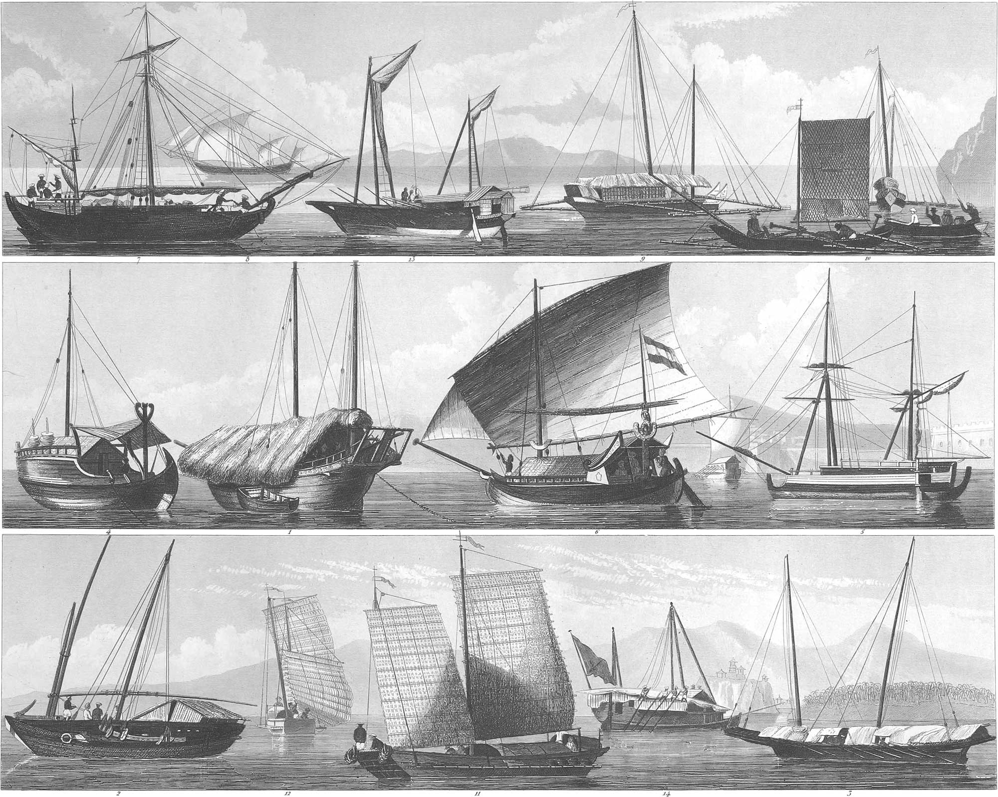
4. Oceanica. There now remains, in our survey of the non-European marine, the portion of the world which modern geographers include under the name Oceanica, composing the Archipelago of the great ocean between Asia and America. We shall follow the celebrated traveller and geographer Domeny de Rienzi in our division of this important portion of the world. According to him, Oceanica is divided into the following clusters of islands.
- The country of the Malays, or West Oceanica, the so-called Indian Archipelago, with the island of Borneo in the centre.
- North Oceanica, from the Tropic of Cancer to the fortieth degree of latitude, on the west to the island of Borodino, and on the east to 167° W. longitude.
- Polynesia, with the West Guidin Islands, Neville, the Caroline, Pelew, and Manner’s Islands, Cocal, the Sandwich Islands, extending to the south of New Zealand; west to the island of Ticopia, and east to the island of Sala y Gomez.
- Central Oceanica, with New Guinea, the Papuan Islands, and the islands inhabited by blacks in the east and south-east.
- South Oceanica, with Australia, Van Diemen’s Land, New Caledonia, &c.
a. West Oceanica, or the Country of the Malays. The close connexion which has always existed between the country of the Malays and the neighboring continent of Asia, enables us to consider the navigation of the two nations also in connexion. The vessels from the Straits of Malacca are here of interest, especially the little pirogues which are known under the name of toucangs. These have departed from the usual form of pirogues, being shorter and broader, sometimes having a slightly curved keel, and sometimes one entirely straight; they have square sails joined together with rice-straw, and rolled up when not in use; the rudder rests on a small platform in the stern of the boat; the oars are rhomboidal, or in the shape of a myrtle leaf Freight ships of a larger size are propelled partly by sails and partly by oars. We have already mentioned the vessels (fig. 6, fig. 3) which form the principal communication between Sumatra and the Malacca peninsula; to this class also belong the large coasters of the Maldives (pl. 5, fig. 9), which, in their construction and the arrangement of the masts, resemble the European cutters. At Sumatra we find a peculiar kind of pirogue, called pulo-rajahs, which are 28 feet long, 5 feet broad, and hewn out from one piece, in the shape of a trough, their sides being raised through nearly their whole length by wicker-work, the upper part of which is kept in its place by beams; the oars are hung on small trestles, and the rudder works in a singularly shaped box at the side of the stern. These pirogues have a mast with a straight square sail. The proas of Achem in Sumatra are coasters which can also be equipped for longer voyages. They lie deep in the water, and their section forms a perpendicular semi-ellipse. They are 45 feet long and 9 feet broad, with three masts, of which the two after masts stand very near the stern. A sort of bowsprit is held in its place by three ropes, on which a jib is rigged; the keel forms a very long semi-ellipse; the vessel is blunt in the stern, and has a rudder on each side; it is provided with a convenient deck, and is nine or ten feet deep in the hold; the masts stand on supports of a peculiar arrangement; the sides are sometimes raised with trellis-work two or three feet high through their whole length; the rigging is more ample than in Asiatic vessels generally.
The Java pirogues are long and slender to an extraordinary degree, consisting of hollow trunks of trees, and their outline forming the larger segment of a perpendicular ellipse. They usually have two masts with triangular sails, and always double balance frames; the rudder is supported at the stern on a trestle. One of the Java coasters is represented on pl. 6, fig. 6, which shows the difference of these vessels from our own in the form of the keel and the arrangement of the masts. The rudder is here, as in almost all Malay vessels, set at the side of the stern-post, and is simply a very long oar. The construction of the Malay vessels, and the arrangement of their sides and deck, are shown in pl. 5, fig. 10, which represents a coaster drawn up on the land; fig. 11 is a Malay anchor. These anchors are of oak; instead of the stock in use with us they have a bundle of bamboo rods, placed, however, on the arms; still European anchors are often used. The vessel in fig. 10 is called a kuguar. It carries three masts, with a straight square sail, and a bowsprit with a jib. The masts are all in one piece. The freight ships in the roads of Sourabaya are very long, slender, and shallow; their transverse section is almost semicircular; they are moved partly by standing rowers and partly by large oblique square sails on very low masts. The long rudder is fixed at the side of the stern-post. The deck is covered with a projecting roof of rice-straw. The prao-pend-jalengs are a kind of small freight boat, one of which is represented as drawn ashore (pl. 5, fig. 14). These boats have a peculiar arrangement for stretching their triangular sail.
In the Archipelago of the Moluccas, formed by the Banda and Gilolo groups of islands, the coasting vessels of Amboyna (pl. 6, fig. 5) possess an uncommon interest, as they combine the nautical construction of the Malay vessels with an arrangement of the masts and rigging very similar to the European. A sort of platform is erected above deck, forming a second deck, under which the cargo and crew find a good shelter. There are also the coasting vessels represented in fig. 4, which have a sort of cabin on the regular Malay frame, while the forward part of the vessel is protected from the rays of the sun by a tent-like awning. The only mast stands near the stern.
The Manado caracores, on the island of Celebes, are a kind of row-boat, used for the transportation of goods. On the sides of the boat, which has a curved elliptical keel with very high ends, there are long beams supporting galleries on their forward end, which is provided with holes, like the columbaria of the ancient ships. The rowers are seated on this structure, with their oars passing through the holes. The galleries are narrower forward than aft. The vessel itself is covered with a roof. These vessels, which are either the model or an imitation of the caracores of the middle ages, have also anchors of a peculiar form, like a disk, with a double quadrangular pyramid passing through it, to the end of which the cable is attached. The rowers also sometimes stand on the galleries, and in that case each boat has but one, and at the same time carries a mast (fig. 14). Another kind of Celebes coaster is shown in fig. 13, in which less account is made of the rowers, as they have two masts.
In the Manilla lagoons, and in the Philippine islands generally, we usually find very narrow vessels, and for that reason the balance frames are employed not only with pirogues, but also with larger vessels, as the coasters (figs. 9 and 11); they have at all events a broader or less projecting platform (fig. 12), in order to guard against upsetting. All these coasters are sailing vessels, and usually have two masts, each of which is made of only one piece. The sails are square and very clumsy, being made of mats like the Chinese. They almost without exception have flat bottoms and blunt sterns. Each ship has two rudders. The passenger boats of Caviteh have open pavilions, with platforms, over which a tent is extended.
b. North Oceanica, Polynesia, and Central Oceanica. On the islands forming these three divisions of Oceanica, the skill with which the natives construct their pirogues and corocoras, or war-boats, is carried to the highest degree of perfection. Pirogues, with one or two balance frames, sailing with great ease and swiftness, and adapted to coast navigation and quiet seas, are in general use among the inhabitants of the Marian and Caroline islands, and in fact among all the Polynesians. The people of the Caroline islands, especially of the Guliai groups, are the most skilful and fearless mariners of Oceanica. Their pirogues are the swiftest and most complete known. These islanders divide the points of the compass precisely in the manner which prevailed among the Greeks and Romans from Alexander to Claudius. At the other extremity of Polynesia the natives use large double pirogues, in the management of which they exhibit quite skilful seamanship. The New Zealanders have splendid war pirogues, without balance frames, but they never go out of sight of land, like the islanders just mentioned, who steer by the stars. These pirogues, which have awakened the admiration of all European seamen, have until recently been the objects on which the natives bestowed all their industry and skill. The simplest pirogues, hollowed out from the trunk of a tree, may be found in many other places, but the double pirogues, or those fitted to each other in pairs, cannot be found in so great perfection among any other people. In Tahiti and the island of Pomotoo, there are similar double pirogues, which are adapted to long trips, carrying a supply of provisions for the sailors, who live in a wooden box erected over the boat. The hull of each of the two pirogues is covered with planks nicely fitted together, carefully caulked, and protected with a water-proof cement. The rudder is remarkable for its ingenious mechanism. These pirogues were formerly ornamented with carved wood-work, which is seen at present in the slender vessels of the New Zealanders. They are everywhere alike, being the remains of the traditional art which these people have preserved. Their excellent finish is surprising, when we consider the rudeness of the tools with which they are constructed. The double pirogues are in use in Tahiti and the neighboring groups of islands, in the Sandwich islands, and the Marquesas. They are not found in New Zealand, as the nature of the bays of that island requires light vessels; yet it would seem as if they had been used there also. All the New Zealand vessels have on their elevated prows a hideous head, with the tongue protruding, this being regarded as an emblem of war and glory. The stern terminates in an image four feet high, representing a god and endless circles. This is evidently symbolic.
![]() Ship Building
Ship Building
 Ship Building
Theoretical Part
The art of ship-building, in all its departments, depends on the laws of physics, especially of statics and dynamics. We must hence consider the points of mathematical and mechanical science which relate to this subject before commencing the description of its practical elements. The capacity of a body to sustain itself wholly on the surface of the water, or to sink partially, is determined by the difference between the weight of the body and of the quantity of water which it displaces; this difference, under all circumstances, must be kept as great as possible.
1. Determination of the Weight. We must first ascertain the entire weight of the vessel, as this is the basis of all subsequent calculations; but a vessel contains such a variety of parts, and they are so irregular, that this calculation is subject to great difficulties. In the calculation of irregular surfaces and solids we have several approximate methods, where strict accuracy is impracticable. For instance, we take a given axis of the body as the line of abscissas, and erect upon it ordinates at equal distances from each other, and the exactness of the calculation will be in proportion to the number of ordinates. From these abscissas and ordinates Atwood determined the cubic contents of an irregular body by the formula \((\textup{S}+2\textup{P}+3\textup{Q})\frac{3i}{8}=x\), S representing the sum of the first and last ordinates, P the sum of the fourth, seventh, and tenth, &c., ordinates, Q the sum of the second, third, fifth, sixth, eighth, and ninth ordinates, and i the magnitude of the equal abscissas. We thus obtain the area of any number of sections taken at pleasure, from which we may easily calculate the cubic contents.
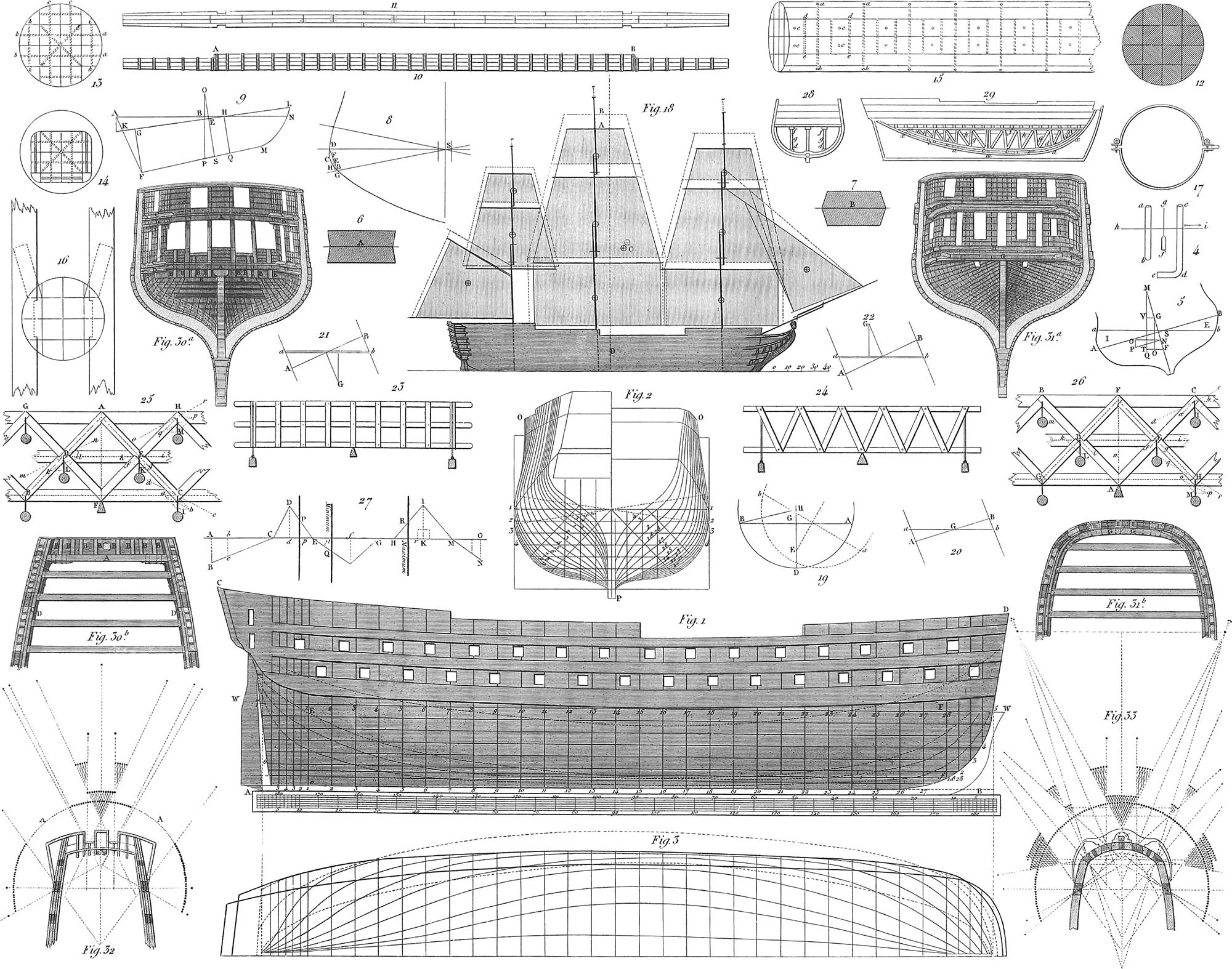
2. Displacement of the Water. We know from hydrostatics that every floating body, whatever be its figure, displaces a portion of the fluid of a weight precisely equal to its own; hence, we may determine the weight of a ship by ascertaining the weight of the water which it displaces. This is a simple calculation, as we have only to determine the number of cubic feet in the part under water, its figure and dimensions being given; but the displacement of the water by a vessel varies with the height of the water-line; the lowest water-line gives the minimum, that is to say, the weight of the ship when she is launched; while the highest gives the maximum, or the weight of the ship after she is fully equipped for service, and with her cargo on board. The determination of this displacement is a problem of great importance. The form of the ship, after it is finished, may certainly aid the builder in the solution, but there are often cases in which we are obliged to go back to first principles, and then the calculation becomes quite complicated. An approximate method has been proposed by Bouguer, who takes the body of the ship as a semi-spheroid, which figure it in fact resembles more than any other; now, since the contents of a spheroid are equal to \(\frac{11}{21}\) of the contents of the circumscribed parallelopipedon, he assumes that we shall obtain the displacement by taking the parallelopipedon formed by the three dimensions of the ship under the surface of the water. The formula given above applied to the body of a ship renders a result so exact, that in ships of 3,000 to 4,000 tons the discrepancy will amount to scarcely half a ton. We must have the ground plan and elevation of a ship in order to determine the displacement (pl. 7, fig. 1). Let ABCD be the elevation of a ship, and WW the water-line, for which the displacement is to be ascertained. Take the points E and F in this line at the distance of several feet from the stem and stern-post, and divide the line EF into several parts at pleasure, using an odd number, however, or a multiple of 3 + 1; through the points of division draw the perpendiculars 1.1, 2.2, 3.3, to 28.28, and the ship will be divided into a certain number of equal vertical parts. Now, let OPO (fig. 2) be a section of the ship, in which the lines 1.1, 2.2, 3.3, 4.4, represent transverse sections to the outside of the ship, at the different heights 1, 2, 3, 4, of the sketch (fig. 1), observing that at the right of our drawing the sections are forward of the centre of the ship’s profile, and at the left are abaft the same. Divide the height under the water-line, WW (fig. 1), into feet, draw horizontal lines through the points of division, so that the ship’s body will be divided into a number of equal horizontal parts, corresponding to the division in the section (fig. 2). Measure half the breadth on the different horizontal lines, according to the scale of the ship, and it will give the value of the numbers required in the calculation. This half breadth may also be found by the plan of the water-line (fig. 3); double the results thus obtained, and it will give the displacement for the portion of the ship’s body between E and F (fig. 1). For the portions forward of Ff and abaft Ee the calculation can be easily made, and the results added to those obtained before. In determining the displacement, some inches must always be added when the ship is at anchor in rough water or at flood tide, or under a press of sail at sea. This is on the principle that a particle of water which is in motion, and reaches the surface of a body, no longer exercises its pressure on all sides, but strives to escape in the direction of its motion, and hence its vertical pressure against the body is diminished, which must accordingly sink deeper than when the water is quiet. The pressure of a particle of water in motion is in proportion to its depth below the surface, less the depth proceeding from the velocity in the direction of the motion. This is shown by an experiment of Romme. He took two tubes (fig. 4), one straight, ab, the other bent, cde; both were open, and so wide that they could admit the float gf, the lower end of which was cork and the upper a graduated rod. These tubes were first immersed in standing water, the float was inserted, and the degree of immersion noted on the scale; they were then placed in running water flowing in the direction hi, the bend of the tube, cde, lying with the stream, when it appeared that the float was immersed one inch deeper. When the bend of the tube was held against the stream, the float rose an inch higher than in standing water. Upon measuring the velocity of the water, it was found to be seventy feet in thirty seconds; and according to the velocity, the water must have risen or fallen in the tube about 1 inch 1 line.
As salt water has a greater specific gravity than fresh, a ship sinks deeper in the latter, making a difference of about six inches in a ship of the line of 120 guns.
3. Centre of Gravity. It is important to ascertain the centre of gravity, not only of the part of the ship displacing the water, but also of the whole body of the ship, since the sailing of the ship depends on the right position of this. The method of determining the gravity of each is explained in Statics, and we need add nothing to what has been said above. In like manner, when we wish to determine the centre of gravity of the immersed portion, we must find also that of the part above the water, it being necessary that they both should lie in the same transverse plane for the ship to sail well. If it appears from calculation that this is not the case, the necessary changes must be introduced.
4. Stability. The stability of the vessel may be regarded in two points of view: first, the hydrostatic, when the floating body is at rest; secondly, the hydrodynamic, when it is in motion. A parallelopipedon whose specific gravity is not more than 0.211 will always float with one surface out of water, but as the specific gravity increases the surface inclines, so that with the specific gravity of 0.75 the diagonal of the body lies in the water-line, and it then always turns in the water. This proposition is of great importance to the ship-builder, as it affects the form of the ship’s body.
It is evident that the resultant of the force exercised by the water in order to sustain a ship, and to counteract its tendency to fall on the side, operates through the centre of gravity of the immersed part, and that the direction of this force is perpendicular to the surface of the water. Hence, when the ship tends to fall over, the force of the water strives to restore it to its place, and the amount of this force measures the degree of stability. Whenever a ship assumes the direction represented in pl. 7, fig. 5, a prismatic body, E, emerges from the water, while another, I, must be immersed. Both these portions, dissimilar as they may be in the form of the ship, are necessarily of equal weight, since the effect of their pressure is the same, and their line of intersection, S, must be straight, and at the same time parallel to the axis of rotation which passes through the centre of gravity G. Let ab be the line which separates the immersed portion from the portion not immersed, G the centre of gravity of the whole ship, F the centre of gravity of the immersed part when the ship stands upright, and Q the same point when the ship inclines to the side. Now suppose QTVM drawn perpendicularly through Q, the lines FT and GV through F and G, perpendicular to QM, and through G the line GO parallel to QM, intersecting FT in O. Now, since in the inclination of the ship the volume E is taken away and the volume I added, and since the contents of every volume are supposed to be combined at its centre of gravity, it follows that the volume E will appear transferred to I; and calling the horizontal distance of the centre of gravity y, we have the momentum yE or yG proceeding from the transference of E. Now, when the ship inclines at the angle ASa, or the equal angle FGO, the water must act upwards in the direction of the line QM, and in proportion to the weight of the ship or its pressure, which we will call D; and the force which is to restore the ship to an upright position, or rather turn it around the axis passing through the point G, is, according to Attwood, D × GV = D × FT − D × FO, and since D × FT, the horizontal momentum produced by the transference of E to I, is equal to the momentum of E, that is, equal to yI, we have D × GV = yI − D × FO = yI − D × FG × sin. FGO. Now putting i for FG, and s for sin. FGO, the angle of inclination, we have the formula for determining the stability of the vessel, D × GV = yI − Dis. The simple inspection of figs. 6 and 7, where A and B represent two ships with equal water lines and equal centres of gravity both of the whole and of the immersed parts will show, that if the side lines of one ship under and over the water form receding angles, and in the other salient angles, both being equally acted on by wind and sails, one ship will have the greatest security and the other be exposed to the greatest danger, although the formula for stability gives the same value in both cases. It hence appears that this formula must be used with great caution and judgment. The actual stability must be determined from the given formula, since in most cases the two bodies E and I are not actually equal, and their line of intersection would lie to the wind side of the water-line. Hence an eccentricity of from \(\frac{2}{10}\) to \(\frac{3}{10}\) of a foot has been assumed in the transverse section of the ship for the line of intersection of these two surfaces. We must, therefore, calculate the contents of the two bodies, whose transverse section is a mixed triangle, one side of which may be regarded without error as a part of a parabola. Having completed this calculation, we must calculate the true contents of the parts immersed and emerged by the inclination, according to the proper formulas, and if it should appear that they are unequal, we must take another point until we obtain this equality. Supposing that we have at length obtained the position of the true inclined water-line, we can proceed to calculate the stability by the formula ∫ WZdx + ∫ wzdx − Dis. The integral of the function WZdx is obtained by the above mentioned sectors; the different values of Z and z are obtained by calculation, and the values of W and w are found by the following method. Let SBD (pl. 7, fig. 8) be one of the sectors, SD the straight, and SB the inclined water-line. The line DB divides the sector into a triangle and the adjacent parabolic surface. Bisect BD at E, draw EG perpendicular to BS, and take EF = \(\frac{2}{5}\) of this line. From E and F drop the perpendiculars EG and FH on SB, and \(\frac{2}{3}\)SG will be the distance of the centre of gravity of the triangle SDB from the point S, measured on the surface of the water, and SH the distance of the same point to the centre of gravity of the curved surface DCB. Hence the formula \(\frac{2}{3}\)SG . SBD . SH . BCD gives the value of WZ for this sector, and applying the formula for the equidistant ordinates (see §1, p. 31), we determine the integral of ∫ WZdx. We make use of the same process to obtain the integral of ∫ wzdx. As regards the function Dis, the displacement D has been already calculated, and s the assumed angle of inclination and the element a, which depends on the true position of the centre of gravity, can only be found by calculation or experiment with a ship of precisely similar construction. We can hence determine the true measure of the stability by the formula D.GV = ∫ WZdx + ∫ zwdx − Dis. A simple method of finding the centre of gravity of the ship’s body has been given by Abethell, who takes his data from docking the vessel, which of course is done at high water, the water passing off with the ebb tide, and then the dock-gates are closed. He takes the time when the extremity of the keel touches the foundation of the dock, as the water passes off. From that time the water gradually leaves the after part of the ship, while the bows are immersed to a greater depth, and an equilibrium takes place between the total weight of the ship and the pressure of the water upon the immersed portion, until the moment when the ship is supported at both ends. During this time the ship is to be regarded as a lever of the second kind, the fulcrum of which is the point where the keel touches the foundation of the dock, while the power and weight, that is, the weight of the immersed part and of the ship’s body act in the perpendiculars which pass through the centre of gravity. All the magnitudes, save the distance of the perpendiculars through the centre of gravity, are known or may be readily calculated. If we now take AN (pl. 7, fig. 9) as the natural water-line, and KL the temporary water-line, where the keel first touches the foundation, we draw QH through the centre of gravity of the volume KFML, perpendicular to KL, and FG parallel to QH. If, then, D be the usual pressure, d that of KFML, and GH = b, draw SEO parallel to QH at the distance GE from G = \(\frac{bd}{\textup{D}}\), it will pass as well as PBO through O, the centre of gravity of the ship, when we have the necessary points for determining the distance, PBO being perpendicular to AN.
5. The Masts and Sails. Theory has hitherto accomplished little in determining the length and proportions of masts. We must, then, take experience as our guide. The position of the masts exercises an important influence on the qualities of a ship, a difference in them often improving the action of the whole vessel. Not less important in the art of ship-building is the form of the sails, for however perfect may be the construction of the ship’s body, without a correct position of the masts and the right number of well-shaped and well-fitted sails, the desired object will never be attained. The wind drives the vessel forward while it fills the sails; they should, therefore, be as large as possible, though there are limits which cannot be exceeded without danger. We shall presently consider the dimensions, positions, and different kinds of masts and sails. The centre of gravity is a matter of importance also in sails. Fig. 18 represents the centre of gravity and the form of the various sails in a ship. The centre of gravity is marked by the sign ⊕. C is the centre of force of the whole system, and D the line of draught.
6. Stowage, Rolling, Pitching, and Falling of a Ship. An important point in the construction of a ship is the stowage, or the distribution of the burden in the hold. We have many examples showing that a ship built on the best model sails much worse than an inferior vessel, because it is not well stowed. The main point in stowage is to bring the centre of gravity as low as possible, so that the ship may resist the action of the wind on the sails with the greatest possible uniformity.
All the calculations of equilibrium which we have thus far presented are disturbed by the action of the winds and sea, and hence new mechanical conditions must come into play. These produce certain motions of the vessel which may exert a very unfavorable influence not only on its sailing, but on its firmness in general. Among these motions is the rolling, when the ship constantly inclines from one side to the other. This is produced either by the shock of a wave against the side of the ship, when it takes place above the centre of gravity, or by the motion of the waves among each other. Pl. 7, fig. 19: let ADB be the transverse section of a ship, AB the water-line, E the centre of gravity of the whole ship, and G the point where the surface of the water would intersect the perpendiculars through the centre of the laden ship, and BH the direction of the force which brings the ship into the position ab. The force which produces this inclination is represented by the line EH, and the force which tends to restore the ship by the line EG. These forces, which act in opposite directions, produce the rolling, and the effect of the acting power is EH + EG. In regard to the motion of the waves, the rolling must commence as soon as a wave rises to one side of a ship and falls on the other. The inclination of the side of a wave gradually increases from its horizontal position to its greatest height, and conversely, thus gradually increasing the force which tends to turn the ship around its horizontal axis; and long before the roll has reached its proper height, it is met by a wave from the opposite side, which destroys its effect and prevents a further bending over of the ship. The axis of rotation here spoken of has been thus far considered as at rest; this, however, is far from being the case; instead of remaining at the same height, it rises or falls, or in fact, as often occurs, is at rest. It is found, for instance, that when there is a tendency for a greater part of the ship’s body to sink on one side than to rise on the other, the axis of rotation must be elevated during the motion. In this case rolling begins and the ship is raised, while it lies on the side, and falls when it recovers itself. The opposite effect is produced when a smaller portion of the ship’s body is immersed than that which tends to rise on the other side. The occurrence and the extent of this motion depend on the position of the centre of gravity and on the form of the ship’s sides between wind and water. Let us investigate the case when the sides of the ship are parallel with the plane of the masts. Pl. 7, figs. 20, 21, 22: let AB be the water-line when the ship is upright, ab the position of this line when the ship is inclined 10°, and G the centre of gravity, which in the upright position is situated in both lines, but above the surface of the water in fig. 22, and below it in fig. 21, then in the first position, when immersion and emersion are equal, the ship in turning will neither rise nor fall; in fig. 21, when the immersion is greater than the emersion, it must rise, and in fig. 22, when the reverse takes place, it must fall. But when the sides of the ship diverge above the water-line, the axis of rotation (fig. 20), instead of being at rest, will rise, as in this case the immersion is increased. In fig. 21, the immersion will increase still more, and the axis, accordingly, will rise still more, and in fig. 22, the immersion will also increase, and the ship will fall only in a slight degree. But when, in the opposite case, the sides of the ship diverge under the water-line, and above it are parallel with the plane of the mast, the ship (fig. 20) will fall as it turns, the rising of the ship (fig. 21) will be corrected, and the falling (fig. 22) increased. It hence appears that whenever the equality between immersion and emersion is essentially impaired, the shock to the ship in violent pitching must be great and dangerous. In order to avoid this serious difficulty, the actual position of the centre of gravity of the ship must be calculated, and such changes made in the ship’s body that when the ship turns on its axis, which passes through the centre of gravity, the immersion and emersion may remain equal. The motions of rolling will be free from all dangerous shocks whenever the ship’s centre of gravity lies in or near the plane of the water-level.
Another kind of rolling, namely that in the direction of the axis of the ship, is pitching, in which the bow of the ship rises and falls. A wave meeting the ship raises the bow, which falls again as soon as the wave has passed, and this action is repeated with every new wave. If a ship is close to the wind, it often happens that when a wave has passed the forward part, the bows fall rapidly and only rise with difficulty at the approach of the next wave; in this case the ship is said to pitch (pl. 21, fig. 2). When a wave has passed the forward part of the ship and arrived towards the centre, a considerable portion of the ship’s body is without support. This portion falls upon the surface of the water with a considerable degree of force, composed of the product of the weight of the whole forward part and the length of the unsupported part. Sometimes this motion takes place at the stern, and then the ship is said to fall. Both cases are equally unpleasant in their effects, as they diminish the rapidity of sailing and expose the ship to great danger. The defects which the ship-builder has fallen into in this respect may often be partially remedied by experienced seamen, if they take great care in the stowage and place the greatest weight in the centre of the ship.
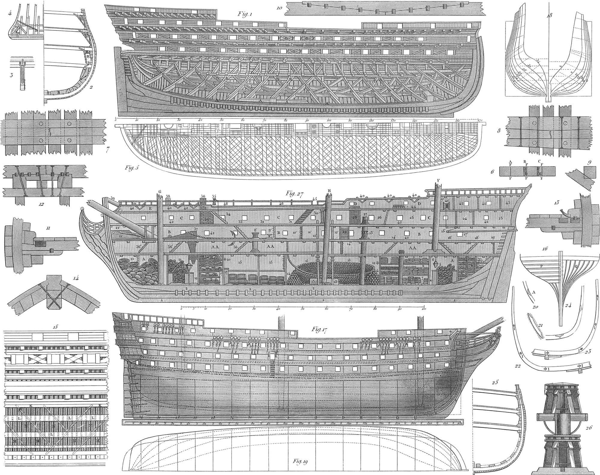
7. Fastening the Body of the Ship. We know from common experience how difficult it is, even in the most simple carpentry, to preserve the shape of a building, and we are hence obliged to use a variety of braces and supports. But in ship-building the preservation of the form is far more important and more difficult, as the greatest danger would arise if the ship on leaving the stocks should become loose in the different parts and not retain its prescribed form. We have examples of such accidents. In ship-building especially theory and practice must go together. It is not only the violence of storms which tends to disturb the form of the vessel, but the pressure of the water even when quiet, which properly sustains the ship, exercises a similar force. If we draw a straight line from the stern to the stem of the ship, while she is still on the stocks, this line will often be deflected some five or six inches as soon as the ship touches the water. This is owing to want of precision in the work. Whole planks and connecting pieces are often forced out of place and broken. The length of a seventy-four is 170 feet or more, and only a slight knowledge of the strength of materials will show that in so great a length the strongest timber must bend under its own weight, and a change of form, therefore, is almost unavoidable. Seppings, one of the best English ship- builders, has endeavored to avoid this difficulty by the plan of oblique bands. We know that a mere quadrangle can never be firmly put together, but that the simplest lattice-work must have an oblique band, in order to hold its shape. If we compare pl. 7, fig. 5, which represents the old system of ship-building, with fig. 6, which indicates the main principles of the new, we shall perceive that the advantages of Seppings’s plan are in proportion to the lengths which we have to deal with. The effect of the triangular system is to give the pressure in the direction of the fibres of the timber, while in the rectangular system the strain comes across the grain. Pl. 9, fig. 1, shows an interior view of the side of a seventy-four according to Seppings’s system, where the diagonal pieces diverge from the other timbers at an angle usually of 45°. In the forward part of the ship, these diagonals run in a different direction from those in the rest of the vessel, and are at a distance of six or seven feet or more from each other. Their upper ends rest against the horizontal frame of the beams of the gun-deck, while their lower ends are supported by the first planks of the kelson, except in the centre, where they meet the planks lying on each side of the kelson in order to receive a part of the pressure of the main-mast, which always bears hard upon the keel, and often with injurious effects. Other timbers are placed in each direction upon the joints of the frame timbers, and connected with the knees and ribs, so as to form an entire system of immovable rhomboidal parts. A beam is placed in each division, in an opposite direction to the inclination of the diagonals, dividing the rhomboids into two equal parts, and according to Seppings these beams are like the key-stone of an arch to the diagonals. This arch-like arrangement of the diagonal timbers not only prevents any change in the direction of the length, but also presents a resistance to the outward pressure from below.
The beam-work in the new system is constructed almost precisely like that of the old, except amidships, where the greatest strength is required, and where Seppings introduces two additional timbers. They are all laid in the inside, either on planks or frames, which are designated by E in fig. 2. They are connected together at different lengths by dovetails or round pins, so that they form a resistance to the longitudinal pressure. In pl. 9, figs. 1 and 2, A is the kelson, with the additional beams; B, the diagonal timbers; C, the lengthwise pieces; D, their braces; E, the inside frame, supporting the upper part of the diagonals; F, supports for the braces between the port-holes; G, braces; H, blocks under the supporting planks and frames for the iron knees, of which we have a front view in fig. 3. In the old system, the deck planks formed nothing but platforms; but in the new system (fig. 5), with the exception of the forecastle, round-house, and quarter-deck, they are laid diagonally, giving an additional support; fig. 4 shows the construction of a ship’s stern on Seppings’s plan, with all the braces and necessary iron-work. The helm-port-transom is here left out, which formerly was one of the heaviest and most unmanageable timbers in a ship.
If we examine more closely the principles of Seppings’s system, which is now adopted in the British navy, we arrive at the following result. Through the point at which the supporting forces act, draw a line representing the direction and magnitude of the draught power, and taking this as the diagonal of a parallelogram, the sides of which are parallel to the supporting forces, draw through the point from which the supporting forces act a line parallel to the former; then all parts of the connexion on the same side of the draught-line will be in a state of pressure, while those on the opposite side are in a state of tension. The first object of the diagonals is to prevent the timbers from bending. If we regard AF (pl. 7, figs. 25, 26) as the neutral line from which the curvature extends to both sides, it is evident that nothing but the construction shown in fig. 25 can prevent it, for since A in this figure is supposed to be one of the neutral points of the system, it must be considered as firm, and the inclination to curvature which tends to displace the points H, C, G, and B, as well as the action on the supports AC and AB, according to the weight applied, will operate to stretch the timbers, which can be prevented only by the application of these bands. But the action of the bands is entirely in the direction of their length, and hence tends to prevent any change of form, so that the force which tends to displace the point C, is removed by the resistance of the brace, AC, and of the band to the firm point F, and thus an additional strength is given also to the point E; the action of the force which tends to displace the point H, in common with C, is set aside by the firmness of the long internal timber AH, and the resistance of the band HF; so that if the materials are sound, no displacement or change of form can take place. If we now consider the opposite construction (pl. 7, fig. 26), it appears from what has been said, that the braces, AC and AB, are exposed to a pressure; and since the point, A, according to the supposition, is neutral, and therefore firm, the pressure must bear upon the point C, and produce a curvature. But the tendency to press upon the point C is not set aside by the action of the band FE, and consequently, since the point F, according to the supposition, is firm, the tendency to extension in the brace must press upon the point, and still more, consequently, upon the point C. The point E, thus acted on, must communicate its own inclination to the band EH, and produce a sinking at the point H. Every part of the framework, from C to H, is thus subjected to pressure, and a change in the form of the ship must be the effect.
According to Dupin, the main principles in regard to the curvature of vessels are the following.
- If a vertical plane divides the ship into two" parts, so that the weight of each part is equal to the weight of the water which it displaces, then the elements of these parts in respect to this plane, that is to say, the tendency to curvature, will be either a maximum or a minimum.
- This inclination will be a maximum, when the infinitely small part which lies on the plane of the element is directly opposite to the plane of the total element.
- The inclination will be a minimum, when the element on the plane acts parallel to the total element.
Let the lines AO (fig. 27) coincide with the surface of the water, the different sections AC, CE, EG, GH, HK, KM, and MO lying in the same. On some of these segments take the triangular surfaces which represent the difference between the weight of the transverse sections and their pressure on the water. On the segment AC = 49, the right-angled triangle = +72 will lie under the water-line, because the weight exceeds the pressure; on CE = 20, the equilateral triangle CDE = -108, stands above the water-line, because here the pressure exceeds the weight; on EG = 50 stands the triangle EFG = +118; GH = Q.Q is too small to be taken into account; on HK = 13.4 is the right-angled triangle HIK = -119, and finally on KM and MO = 17.5 and 19.5, the triangles IKM and NOM = -115 and +192. Now add together the lines, and we have 176 feet as the length of the ship, and foe the sum of the differences + 37, so that 37 tons must be removed from the forward part of the ship on account of the pressure, in order to set aside the tendency to curvature.
A curvature often appears in the keel, which is sometimes bent more than two feet in the centre. Since such deflections take place, we must find the means of guarding against them. This must be effected in a manner to interfere as little as possible with the stowage. Pl. 7, figs. 28 and 29, show such an arrangement, in which we must bear in mind that the same space will also hold a certain number of water-casks. Fig. 28 is the transverse section; fig. 29, the longitudinal section; a, the frame timbers; b, the cross-pieces; c, the beams over the kelson; d, the floor timbers; e, the filling between the cross-pieces, the floor timbers and their frames; f, frames under the deck-beams, consisting of two thicknesses bolted together in order to give the necessary firmness; g, upright supports; and h, diagonal braces and bands. All the parts must be secured in the best manner to the original body of the ship.
8. Prow and Stern. The most ancient nations ornamented the prows and sterns of their vessels with rich and often with very clumsy work, of which we find some specimens in the middle ages. But in the year 1796 the fashion of clumsy ornaments on the prow was set aside in England, and galleries and carved work on the stern were also dispensed with. In 1811 the plan proposed by Seppings of making the prow round was introduced, and in 1816 the same shape was adopted for the stern. This secured the stern against the beating of the waves and the shot of the enemy, while it also gave occasion to apply new means both of attack and defence. The gain in point of mechanical strength by this arrangement is evident from a glance at figs. 30b and 31b and a proof of the advantage in an engagement is shown in figs. 32 and 33, which represent the sterns of the frigates Boadicea and Hamadryad. In fig. 32, there are spaces at A where the guns do not range at all, which is not the case in fig. 33. Fig. 30a shows the interior perspective view of a straight stern, and fig. 31a that of a round stern.
Practical Part
Ship Carpentry
After the plan of the ship has been drawn by the naval architect according to theoretical principles, it belongs to the ship carpenter to execute the model, which also demands the co-operation of numerous other mechanics. Small and flat vessels are always built without any special arrangements, but for large ones places constructed for the purpose are required, as the so called dock-yards, lying near the water. Stocks made of oak blocks are used for the foundation, with their surfaces lying oblique to the water.
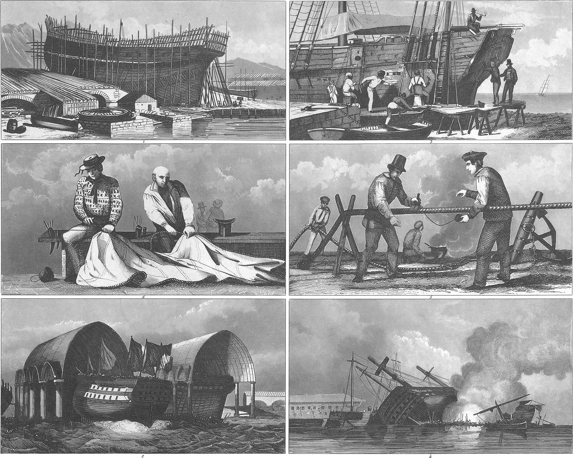
1. The Frame. The building of a ship properly commences by laying the keel on the stocks. This is a beam composed of several pieces, which forms the foundation of the vessel, and receives the whole length of its under portion. Its height is made greater than its breadth (l\(\frac{1}{2}\) lines to a foot of the ship’s length; and 10\(\frac{3}{4}\) lines broad to an inch in height) in order to guard against leeway and to increase its capacity for bearing weight. The stem and stern-posts are mortised to each end of the keel at obtuse angles. The former consists of one or more pieces of curved timber, of equal strength with the keel. Behind this is placed the apron, which is of equal breadth, and one third thicker. A knee passes under it to secure it with greater strength to the keel. The stern-post stands inclining back from the keel, in its mortise called the heel. Its thickness equals that of the keel; its breadth increases towards the lower end five lines for every inch in height, and lessens about one eighth at the top. It also has an apron, with a knee. In large ships there is another post on the outside, which receives the sockets for the rudder pintles. The stern-post must have great strength, as it bears the rudder and the beams which form the stern-frame. The principal timbers in this are the transoms and fashion-pieces. The transoms are placed crosswise of the stern-post, to which they are bolted. Their ends are fastened to the transom knees. The fashion-pieces are similar to the transoms, but shorter, and also bolted to the stern-post and the transom knees. Besides these are the braces between the bottom of the stern and the transoms. As soon as the stern and stem-posts are erected, a rope is stretched from one to the other, perpendicularly over the keel, in order to guide the carpenter in the symmetrical construction of the remainder of the vessel. The inside timbers (the bow timbers and quarter timbers), consisting of several pieces, are then placed at certain distances on each side of the keel. The form of these timbers, which make an arch of more or less curvature, together with the position of the stem and stern posts, determines the shape of the ship’s body. These timbers are either placed directly on the keel, or on planks with which it is covered. A strong piece of timber, called the kelson, is placed over the ends of the timbers resting on the keel, and bolted to them and the keel. These timbers are protected by thin ribbons of wood, running the whole length of the vessel, which are removed when the vessel is planked. Pl. 8, fig. 1, represents a ship of the line on the stocks.
The deck timbers are then placed across the ship, which not only support the deck planks, but also hold together both sides of the ship.
All the parts of the frame are made of oak timber, and are fastened with iron or copper bolts and nails. In the East Indies teak-wood and oak are used, and in South America and other warm countries mahogany and cedar. In Sweden and Norway fir timber is also used, but this is wholly unfit for ships of war, since it is splintered by gun-shot, which is not the case with oak timber, a cannon ball passing through that making a round hole.
2. Planking. When the frame is completed, the main or outside planks, which form the covering of the vessel, are laid on the ribs throughout its whole length. These form the principal connexion between the different parts, and protect the vessel from the pouring in of the water. The bottom planks are grooved to the keel; the ends of the fore and aft planks are attached to the stem and stern-posts in the same manner, but are connected with each other only by close joints. The narrow space between two planks is called a seam, and is caulked with oakum and coated with hot pitch (pl. 8, fig. 3). After the vessel is caulked, the remaining pitch is scraped off. When subsequently the caulking is repeated on the water, it is burnt off (pl. 8, fig. 4). The planks are fastened with strong nails, and also with screw-bolts. The cross seams are made to come on good timbers, and the different courses must be jointed at least five feet apart. In ships of war, the cross seams must not come over or under the port-holes. The thickness of the outside planks varies. The bark-planks, which go round the body of the vessel like a belt and form a projection, are twice as thick as the others. Large ships of war have several courses of these planks. The planks on the bow and under the chain-plates are as strong also, the rest are weaker. In large ships, the outside planks are four and a half inches thick, and in small vessels never under two inches. The planks on the bow are warped by fire. The sides of the ship are also covered with planks inside. Sometimes a course is here and there left open, in order to give the air access to the timbers. In ships of war, the French have found an advantage in filling the space between the planks with cotton, in order to weaken the force of cannon balls.
The planking being finished, the next step is to construct the decks. The larger class of ships have several decks. In ships of war only those which carry guns receive that name. The rest have different names, for example, forecastle, orlop, quarter-deck, and so forth. The decks are composed of timbers lying crosswise, and planks placed over them lengthwise. The beam ends rest on a frame of strong timbers which run from the stem to the transoms, close to the ribs. At the head they are joined to the side-timbers with wooden or iron knees. In the centre, the beams are supported by upright posts. Their distance from each other depends on the position of the masts and hatchways. Half-beams are added when they stand too far apart. The largest beam lies amidships, and is called the sail-beam or the main-beam. The beams of the lower deck are shorter than those of the upper, as men-of-war have the heaviest cannon on the lower deck, and in general all the heavy parts must be placed as low as possible. The decks are slightly raised in the centre, so that the water may run off at the sides, passing through the scuppers, which are small holes lined with lead. The decks also sink a little fore and aft towards the scuppers which are at each end.
3. Finishing of the Construction. After the carpenters have completed the decks, they proceed to construct the hatchways, the ladders, the mast steps, the chain-wales, the pumps, the capstan, the railings, and the hawser-holes, and if the vessel is a man-of-war, the port-holes. The hatchways are square openings, like trap-doors, leading from one deck to another. Ships of war have five or six hatchways; merchantmen usually have three, the main hatchway and the fore and aft hatchways. The main hatchway lies forward of the main-mast, the fore hatchway aft of the fore-mast, and the aft hatchway abaft of the main-mast. There is also an opening at the mizen-mast, but this is called the door, and the sky-light of the cabin. In order to prevent the water from running through the hatchways into the ship, they are surrounded by a frame six inches high (the coamings), and covered with caps and tarred sailcloth, tarpaulin; when they are open a wooden grate is placed over them. In ships of war, nearly all the hatch-ways are provided with convenient ladders, but in merchantmen only those which lead into the cabin and forecastle. The ship is reached from the water by ladders, called accommodation ladders, extending at the forward end of the quarter deck from the water to the sides. One is on the starboard side and another on the larboard. (If one stands at the stern of a ship and looks forward, the side on the right of the mast is called the starboard, and on the left the larboard). The accommodation ladders are of different kinds; those on the starboard side are used only by the officers and visitors. In ships of war there is a broad wooden ladder held obliquely by supports, and for the sole use of the captain and superior officers; the ladder ropes are covered with red or green cloth. Besides these there are state ladders, with iron railings and landings, used when the ship is visited by admirals or royal personages; ladies and invalids are drawn up on the deck in an arm chair, which is raised by a tackle attached to the main-yard.
The mast steps are blocks of stout timber, surrounding the heel of the mast; those for the foremast and mainmast are on the kelson, and those for the mizen-mast on the beams of the lower deck.
The chain-wales are strong planks bolted edgeways against the sides of a vessel, abreast or abaft of the masts, and serving to keep the shrouds from the sides of the vessel; they are fastened above and below with knees, clamps, and chains, to the planks and timbers.
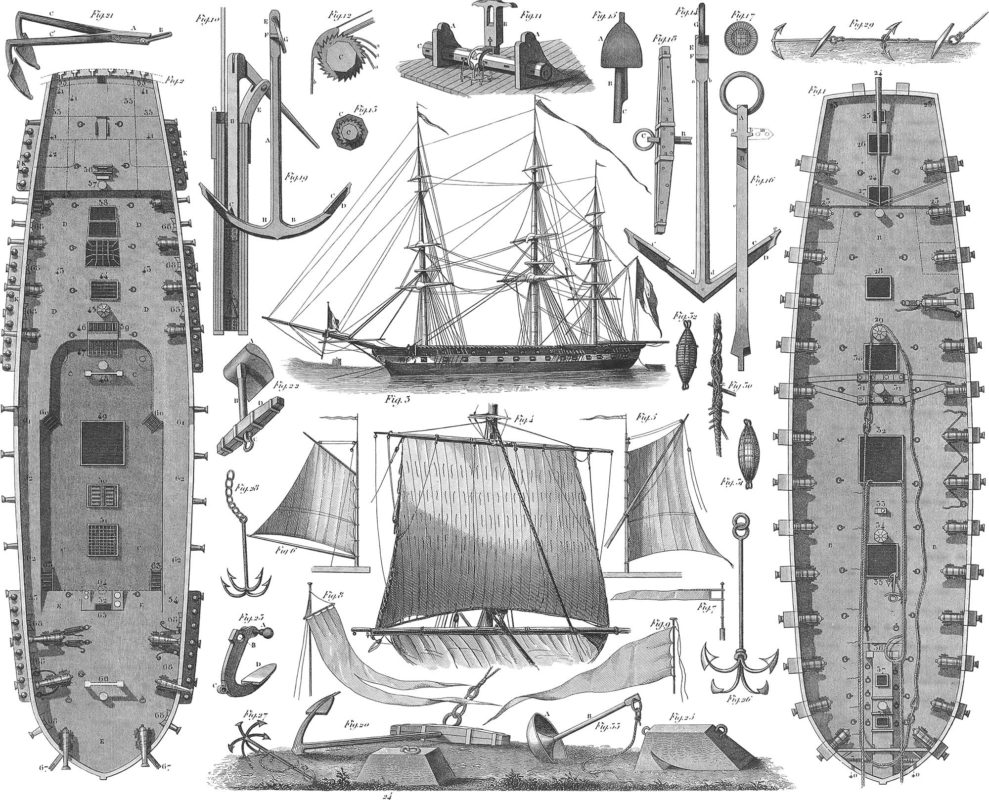
The ship’s pumps (pl. 10, fig. 10) stand near the mainmast and abut below between the timbers, where the water which finds its way into the ship is collected. In large ships of war they do not rise above the lower deck; together with the masts, they are surrounded by a case of strong boards to protect them from injury. A is the pump-stock; B, the upper barrel; C, the upper box, and D, the lower box, both with suction and pressure valves; E is the support for the handle; and G, the upper case, with a spout. Merchantmen usually have only two pumps on each side; men-of-war from two to four, according to their size. Chain pumps are used in the British navy, which are worked with wheels or drums, and have been found very effective.
The capstan (pl. 9, fig. 26) is a windlass to heave up the anchor, or to raise other heavy burdens; it consists of an upright shaft, in the shape of a truncated cone, around which the rope which lifts the burden is wound; in the upper part there are square holes, into which the sailors thrust the hand-spikes in order to turn the capstan; at some distance below there are notches, in which are placed iron pawls, to prevent a recoil. Large ships of war have capstans with internal wheel-work; such vessels have three capstans. The main capstan is placed on the lower deck, abaft the mainmast, and its shaft extends to the kelson; above, it passes through the beams of the upper deck, forming a second capstan, which increases the power of the lower one. The forward capstan stands on the upper deck, between the mainmast and the foremast, and the other capstan on the forecastle.
The common windlass (pl. 10, fig. 11) is used in merchantmen; it stands on the forecastle, between the foremast and the prow, extending horizontally across the vessel. It consists of an octagonal axis, C, which, at the socket A, is made round; the heads are octagonal, and have holes for the handspikes; aft of the windlass is the post, G, on which also the ship’s bell is hung, bearing the tooth-work (fig. 12), with the pawls, aa, and the support, b. A tooth-work wheel, c (fig. 13), is attached to the windlass, C, in which catch the pawls, aa (fig. 12). But if the windlass is to remain at rest, it is secured by the large wheel (fig. 12), which is moved by the support, b.
All the parts of the deck which are in the open air are surrounded on the outside border by an inclosure, consisting principally of the bulwarks, which are a continuation of the timbers lined with planks, and covered with a plank on the top. The bulwarks are usually from three to four feet high; the almost semicircular part surrounding the bow, the arch of the forecastle, is the highest. The railings are covered with thin boards, which in some places are made to turn on hinges, especially at the part of the deck on both sides of the bow and main hatchways; in ships of war, the gangways. In small merchant vessels there is no railing, and a bar or small rope is used instead. The bulwarks in ships of war are differently arranged, and higher throughout, at the quarter-deck being from five to six feet high. The railing is made of double iron posts, with holes at the upper end, through which a strong rope is drawn; from this rope a net-work of small cords is fastened to the bulwarks on both sides, between which, during the daytime and when preparing for battle, the hammocks of the crew are stowed and covered with tarpaulin.
The hawse-holes are round holes in the bow, near the stem, for the cables; they are lined with lead or copper, so that the water cannot penetrate to the timbers of the ship (pl. 12, fig. 3, L). Behind the hawse-holes is a trough in which the water dropping from the cable is collected, and passed off through the scuppers.
The port-holes are embrasures in the sides of a vessel through which the cannon are pointed; they are surrounded by a frame of strong posts, consisting of upper, lower, and side supporters, and are closed with shutters, called port-lids, hung on hinges, and drawn up by a rope inside.
Besides the parts of the ship now described, there are others arranged at the same time; for example, the cat-heads, being two beams, with light carved work, which project over the bow on the right and left of the forecastle; the outer part has metallic disks on the forward end; the inner goes down to a deck beam, to which it is bolted. They are used, after the anchor has been heaved up above the water by the windlass, to suspend it clear of the ship and ready to be dropped.
The arrangements for belaying the running rigging are of different kinds. There are belaying-pins, cross-pieces, cleats, and others. Belaying-pins are iron or wooden pins, placed in the rail at the mast or at the side. Cross-pieces are distributed along the bulwarks, consisting of two vertical and two horizontal pieces; the upper ends of the head-pieces are sometimes at a distance from the rail, and spread apart from each other, so that the fore and main jeers and other large ropes may be made fast to them. Cleats are small pieces of wood with two diverging arms, which are nailed to the railing or to the masts.
The last work on the ship before launching is the completion of the stern, with its ornamental parts, the arrangement of the stern and quarter galleries and of the ship’s head, the sheathing of the ship’s bottom with copper, and painting the ship. The stern is the most ornamental part of the ship, and is often decorated with carving. The name of the ship is inscribed under the cabin windows; on the taffrail over the stern is the flag-staff for the national colors. Ships of war have here the large lantern.
Galleries are found only in men-of-war and large merchantmen. The quarter-galleries pass round on the side of the cabin, with which they are connected by a door; they are generally closed in; the larboard gallery has a water-closet, and the starboard other conveniences. Two-deckers have two galleries over each other; the upper one is generally open. The stern-gallery is a walk four or five feet in breadth, running before the cabin windows, and communicating with the cabin by a glass door. Three-deckers have two such galleries.
The ship’s head, like the beak of the ancient vessels, forms a projection on the bow, consisting of several pieces and connecting with the stem. It aids the ship to cut the water, and gives greater firmness to the bowsprit by rigging; but its great use is to enable the ship to lie close to the wind; and as it is embellished with carved work, it forms an ornament to the vessel. It has a gallery with railings, the floor of which usually consists of lattice-work. The washing of the ship and the butcher’s work are done here.
The coppering of the ship’s bottom consists of plates of the thickness of sheet-iron, nailed to the planks with copper spikes; it reaches only from the bottom to the water-line. It serves to protect the vessel from worms, barnacles, and sea-weed. The ship is painted as soon as the coppering is completed; the usual color is black, but the ornamental parts are touched off with yellow or white. All the other work is done after the vessel is launched. Launching is an occasion of great ceremony (pl. 8, fig. 2); the ship either slides down on a cradle, or directly on the stocks. The ship is dressed with flags and banners, and the officers, invited guests, and numerous strangers are on board; and as soon as the last prop is knocked away, and the rope which holds the ship on the stocks is cut free, the crowd of people on the deck, with their motions, cause the ship to quiver, and she begins to glide slowly at first, and then with a rapidly accelerated motion. All the timbers of the ship crack; the keel is so heated by the friction that it takes fire, and water must be poured on. As soon as the ship touches the water she makes a plunge, but soon rises, and shoots forward in the water.
The first thing after the vessel is launched is to ship the rudder. This is hung by strong hooks, called pintles, to the stern-post, and swings like a door on hinges. It is made of oak timber of equal strength with the stern-post, and passing down to the same depth. On the back of the lower part there is another piece of timber, shaped like a wedge, with the point turned upwards. To this is attached a third piece of similar form. They both reach only to the surface of the water. The upper part of the timber passes through the helm-port. There is a square hole in the rudder-head, through which the tiller passes which turns the rudder. As the tiller exerts a great power, it cannot be worked by hand. Two ropes are, therefore, attached to its forward end, running on blocks along the two sides of the ship. These are called tiller-ropes. They pass in opposite directions over an upright wheel, with hand-spokes. As the wheel is turned, one rope winds, while the other unwinds. The rudder is thus moved without difficulty, and its position can be ascertained every moment by the tiller rope. In large ships of war, double wheels are in use (pl. 21, fig. 2).
4. Rules for Ship-Building according to Seppings’s System. All the timber should be thoroughly seasoned. The tenons of the timbers in the largest ships should never be less than three inches thick. Where timbers are to be joined together, at least two 1\(\frac{1}{4}\)-inch bolts must be used. If seams should appear, on account of the timber not being thoroughly seasoned, they must be closed up with great care. It must also be provided that every seam should lie higher on the outside than on the inside, so that if the water should get in, it may flow off towards the inside of the ship. Seams of more than three inches in width are to be filled with pieces of timber consisting of old oak, and altogether free from sap-wood. The fibres must run parallel with those of the timbers which are to be closed. Seams of less than three inches in width are filled with double wedges, driven at the same time on the outside and the inside of the ship. The front of these pieces while drying must be dressed with oil and tar; for this purpose, small holes are often bored in their head and oil poured in. Pl. 9, fig. 6, shows a seam closed up at A, an opening of less than three inches at B, and an opening of more than three inches at C. D is a filling with wedges, the fronts of which are both inside and outside; E is a usual filling where the fronts appear above and below; F are seams which must be caulked. All the planks are to be fastened to cross-pieces, as in fig. 7, their joinings being made to correspond. The clamps are secured to the framework in the same manner, with the addition of vertical bolts, as in fig. 8. In order to bring the diagonal timbers as near as possible to the supporters under the frame-pieces of the gun-deck, a corner of six inches may be taken from the bottom of the beam of the upper course, as in fig. 9. If frame-pieces for the upper deck of sufficient breadth are not to be procured, we need not hesitate to join the sides of the timbers, so as to form a wedge-shaped piece connected by double notches, as in fig. 10. In order to avoid the accumulation of water on the upper side of the water-ways, they must spread in from the timbers so as to lie deeper than the connecting pieces, as in fig. 11. The joinings of the water-ways must be so arranged that they will fall on the centre of the kelson, and that the descending part of the channel below the joining shall be in the direction of the side of the beam, as in fig. 12. The diagonal seams under the water-ways must be thoroughly caulked, for which purpose the curved iron stoppers are used, as shown in fig. 13. A plan of convenient cross-bolting is shown in fig. 14. Here especially no unseasoned timber is to be used. Fig. 27 shows a longitudinal section of an English 120-gun ship; figs. 18, 19, plans. The manner in which merchant ships are built is by no means suited to the present demands of ships of war. The joinings of their timbers and frames and the arrangement of their materials are of such a character, that while one half forms a kind of arch, the other half and the connecting pieces are only loosely put together, and are secured by the planks instead of giving to them a firm support, as they should do. Such vessels can never have the same stability as if all the parts were connected in the manner of an arch, according to the plan proposed by Seppings.
There is a great defect in the manner hitherto adopted of joining the separate parts of the same timber. This is usually done by the addition of a third piece, a, shaped like a wedge (pl. 9, fig. 20). More than 550 such pieces are used in a 74-gun ship, and no fewer in an East India merchantman of 1200 tons. On thoroughly overhauling a vessel for repairs, not one of all these pieces is found to be in good order, and they moreover, will be found to have damaged the timbers to which they are applied. Besides, the timbers cannot be bent sufficiently without destroying their fibres. There is a great loss of material also by cutting off the corners of the timbers which are to be connected by the wedge-piece. No doubt, these pieces were first made use of when none but too short or imperfect timber was to be had (fig. 21); but the requisite curvature can be obtained by a peculiar arrangement without such a great loss of material. The frames of merchantmen, before they are joined together, are partly shown in fig. 24, and too often, in consequence of bad work, the parts are often not accurately fitted to each other, nor to the timbers with which they are connected. There are, moreover, many defects in the connexion with the keel. In order to obviate all these difficulties, Seppings proposed the combination (figs. 22 and 23), in which the connecting timbers are a little shorter and not so much bent, nor so much cut through the fibres. The connexion is also made firmer by using a pin (I) instead of the wedge-piece. Another advantage, finally, is that when the ship grounds the timbers give the whole structure more firmness and support, as is shown by the dotted line at the bottom of fig. 23. In regard to the general security of the arrangement, it will be seen from figs. 25 and 15 that the timbers regularly cross the keel, and that the frames in the vicinity of the lower deck at K compose a firm ship’s body, while only a few courses of planks, L, are applied at the joining of the timbers in order to give greater strength at these places. The other inside courses of planks may be left out, and instead of them double upright pales placed between the planks and the timbers, as at M. This gives more room for stowage. Water-ways, N, between the planks conduct the water to the pumps, which now reach the water themselves, and hence there may be standing water in the space, as all the gutters can be easily cleaned. The timbers which (as in pl. 9, fig. 25) are fastened directly to the sides require no knees, or only very small iron ones. Fig. 16 shows, in the part P, the old system of fastening the beams to the stern-post by transoms, and in the part Q, the new system with curved timbers, which do away with the need of transoms.
Outfit of the Ship
The outfit of a ship includes all those parts not immediately belonging to the ship’s body, but which are necessary to the service and action of the ship. Among them we reckon the spars, the rigging and tackles,. and the sails. By spars we understand masts, yards, booms, gaffs, and all the small pieces used to support the rigging and sails. The rigging comprises all the ropes employed for the support of the masts, the management of the sails, and other uses on ship-board, with the exception of the largest and most important, namely the cables, which are reckoned with the equipment, as they always go with the anchors. The tackles include all the blocks (rollers or pulleys) through which the running rigging passes, to add to the purchase.
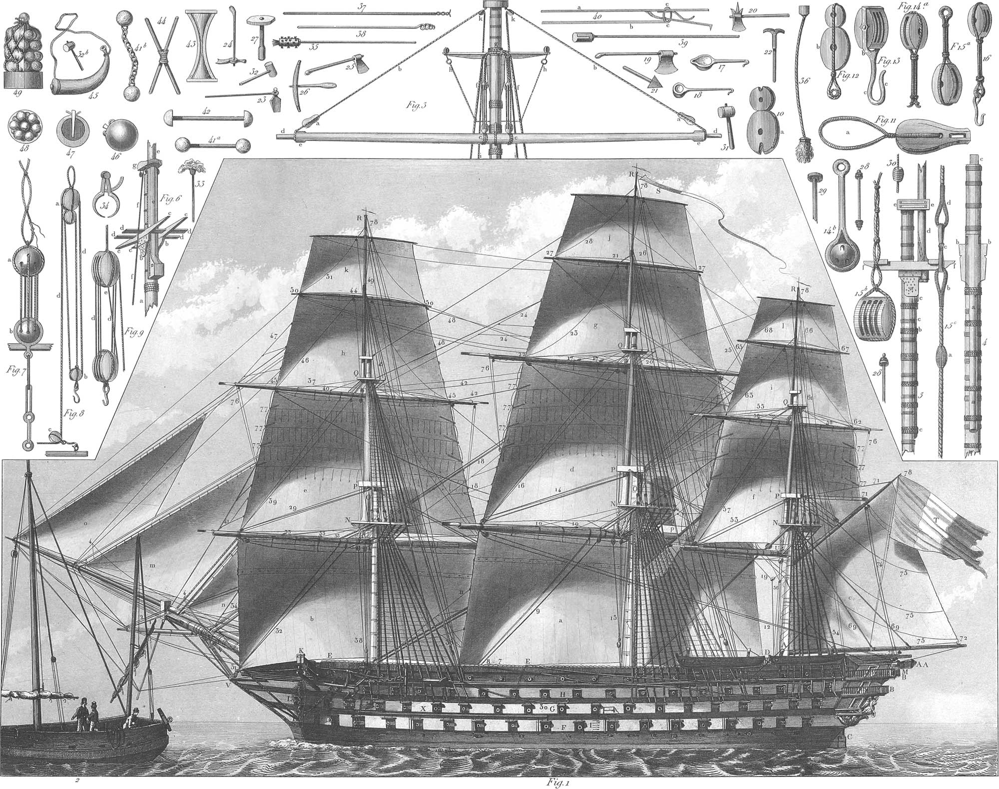
In describing these various subjects, we will take as the model the French ship of the line (pl. 11, fig. 1), carrying 120 guns, and 205 feet in length and 54\(\frac{1}{2}\) in breadth, the large ships of war being the most complete in this respect, and containing everything which in smaller vessels is either not found at all or only to a limited extent. We would premise, in general, that all the fixtures which have the same object, or nearly the same arrangement, are called by the same name, and are distinguished from one another only by the special name of that part to which they are chiefly appropriated.
1. The Spars. The frame to which the rigging is attached, and by which the sails are secured and held firm, consists of what are called spars. These are in proportion to the breadth of beam or to some other part of the ship, so that a practised eye can determine the size of a large ship from a single piece. Of the spars, the masts are the most important, and of these the main-mast takes the lead, as it gives the scale for the rest. The masts, like all the spars, in general, are made of pine or fir. As no single tree is often found sufficient for the length and thickness required in the masts of men-of-war, they are composed of different pieces. A method of constructing masts has recently been introduced by Seppings, which has the advantage of great simplicity and of using shorter and weaker timber than was required by the old plan. According to this arrangement, the largest piece for a main-mast is only 40 feet long and 10 inches thick, whereas formerly timbers were used 84 feet long and 22\(\frac{1}{2}\) inches thick, a mast costing $6,500 for an 84 gun-ship, while the cost now is not much over $1,600. The new method, moreover, on account of its extreme simplicity, admits of repair with far greater facility. Pl. 7, figs. 10–17, show the construction of the masts on Seppings’s system; fig. 10 is the side view; fig. 11, the front view of a main mast. Fig. 12 is a horizontal section between A and B in fig. 10, showing the equal and parallel arrangement of the different parts which compose the mast. The section (fig. 13) shows the application of the wooden bolts in the centre-piece, and fig. 14, the same in the end pieces. Fig. 15 shows the arrangement of the bolts lengthwise. Fig. 16 exhibits the mast, and Fig. 17 is a screw-ring, for binding the different parts together. To secure an equality of force on both ends of the halves composing this ring when screwed together, little pieces of soft wood are placed between the lips.
When the mast is put together, the faces of the different parts are joined by pins of three inches in diameter and six inches long (fig. 11), and the four centre-pieces which form the spindle of the mast are fastened together diagonally by wooden bolts, ed (figs. 13, 15), an inch and a half thick, and at two feet distance from each other. Every couple of the outside pieces is fastened at ih at distances of two feet (fig. 13) with bolts, one and three-quarter inches thick. The whole mast is then nailed at a, b, and c (figs. 13, 15), with spikes, one and five-eighth inches thick, and at least one foot apart. At the ends of the masts (fig. 14) iron bolts, seven eighths of an inch thick, are used instead of the tree-nails, ih (fig. 13). The mainyards, as well as the masts, are composed of separate pieces; this does not diminish their firmness; on the contrary, their elasticity is thus increased. In order to put a mast into its place a scaffold is built on the upper deck, usually composed of two strong beams erected opposite each other, and their ends meeting at the top; these are supported by stout ropes on all sides. The mast is drawn up by a powerful tackle, and passed through the deck to its step on the kelson. One mast being raised, there is less difficulty with the rest. In many ship-yards there are permanent machines for raising by means of which the operation is performed with great ease (pl. 31, fig. 3)
The different spars are the following:
The main-mast (pl. 9, fig. 27 H), standing not in the centre of the ship, but towards the stern, at the distance from amidships of 7\(\frac{1}{2}\) or 8 lines to each foot of length; in the present case, therefore, about 10 feet 8 inches. It does not stand perpendicularly, but inclining backwards, in order to give more room forward to the sails, and to diminish their pressure on the bow. Its length is twice the breadth added to the depth of the ship (132 feet), and in frigates rather more. The greatest diameter is three inches for every ten feet in length (3\(\frac{1}{2}\) feet). Everything pertaining to this mast receives the epithet main. The pieces around the spindle (pl. 11, fig. 4a, and fig. 5c) constitute the mast-casing.
The main-top (fig. 1 N). Although the tops are not spars, yet, as they are so closely connected with them, they must be described in this place. These are scaffolds around the upper part of the masts, O, consisting of four beams, called trestle-trees, covered with boards. Two of these timbers, cc (fig. 6), are placed lengthwise on each side of the mast, supported by cheeks, b (figs. 4, 6); the two others, dd, pass over these, crossing them fore and aft of the mast. On the trestle-trees a platform is erected, with holes for the rigging, the forward edge being curved and the after edge straight. It is surrounded by a railing with a covering of tarpaulin or network. The tops serve to support the top-mast rigging, and to hold the men who keep watch in them, or who have work to do there (pl. 25, fig. 6). They were once often used during an engagement for the discharge of small arms, but this practice is now generally discontinued.
The cap, P (pl. 11, figs. 1, 5ee, 6g), is a strong thick block of wood, connected with the top of the mast by a square tenon, c (fig. 4); the forward end has a round hole, through which passes the foot of the topmast, d (pl. 11, fig. 5, and e, fig. 6).
The main-top-mast is the first prolongation of the main-mast, and is one and a half times the breadth of the ship in length (81 feet 8 inches). Its thickness follows the proportion of the mast. This mast is secured partly by the cap, and partly by the trestle-trees and fid, a block of wood placed through a hole in the heel, and resting on the trestle-trees, which prevents the mast from sliding down. At the heel of the top-mast is the top-block, through which the top-rope is rove in raising or lowering the mast.
The main-top-mast cross-trees, Q (fig. 1), form a light frame of four pieces of timber placed across the head of the top-mast, but without any top. Everything above these cross-trees is called top-gallant and royal.
The main-top-gallant-mast is the second prolongation of the main-mast, arranged in the same manner as the main-top-mast, and measuring three fifths of its length (48 feet). Ships of war usually carry top-gallant-masts of different lengths, which can be changed according to the weather. To the shorter one only one top-gallant-sail is attached; but the longer one, which is nearly as long as the top-mast, bears two sails, one over the other, the top-gallant-sail, g, and the royal, j.
The main-truck, R (fig. 1), is a circular piece of wood on the head of the top-gallant-mast, fitted with a sheave, to draw up flags and signals. The general term head is applied to the upper end of the masts and top-masts, reaching from the trestle-trees to the cap, and from the joining of the top-gallant-mast to the truck. The entire mast, with the long top-gallant-mast, is 248 feet in length.
The main-yard (fig. 3dd). The term yard is applied to the spars which are hung across the masts with rigging, and to which the sails are attached. The length of the main-yard is twice and one-quarter the ship’s breadth (122 feet 4 inches); the thickness is 2\(\frac{1}{4}\) inches for every ten feet in length; the diameter in this case, therefore, is 2 feet three inches, decreasing about one third at both ends, dd.
The main-top-sail-yard is \(\frac{7}{10}\) of the main-yard (85 feet 7 inches); the main-top-gallant-yard is \(\frac{4}{5}\) of the ship’s breadth (43 feet 6 inches); and the main-royal-yard \(\frac{1}{2}\) of the ship’s breadth (27 feet 2 inches).
The fore-mast, G (pl. 9, fig. 27), stands at about one tenth of the ship’s length aft of the stem (20 feet 6 inches); its length is nine tenths of the main-mast (118 feet 10 inches); the thickness is in the same proportion to the length as in the main-mast. In the top and the other arrangements the same system is employed, all the parts being designated by the term fore, as fore-top, fore-sail, &c. The fore-top-mast is one tenth shorter than the main-top-mast (72 feet long, and 1 foot 10 inches thick). The fore-top-gallant-mast, the second prolongation of the fore-mast, is five sevenths of the ship’s breadth (39 feet). The fore-yard is double the ship’s breadth (108 feet 10 inches long, and 2 feet thick). The fore-top-sail-yard is once and one third the ship’s breadth (72 feet 6 inches long, and 1 foot 3\(\frac{3}{4}\) inches thick). The fore-top-gallant-yard is seven tenths of the ship’s breadth (36 feet long, and 9\(\frac{1}{2}\) inches thick), and the fore-royal-yard is in the same proportion to the fore-top-gallant-yard as the main-royal-yard to the main-top-gallant-yard (23 feet long, and 5\(\frac{1}{8}\) inches thick).
The mizen-mast (pl. 9, fig. 27 F) stands two thirds of the ship’s breadth from the stern-post (36 feet 3 inches). It reaches only the first deck, where its heel is fastened, while the two other masts touch the kelson. All the parts connected with it have the name mizen applied to them. The breadth of the ship added to twice its depth gives the length of this mast (100 feet 5 inches long, and two feet 6 inches thick). The mizen-top has the same relation to this mast as in the two others. The mizen-top-mast is the first prolongation of the mizen-mast, its length being equal to the ship’s breadth ( 54 feet long, and 1 foot 3\(\frac{1}{3}\) inches thick). The mizen-top-gallant-mast is the second prolongation of the mizen-mast, but is not used in all ships, and in that case the mizen-top-mast is lengthened out one third, and bears the mizen-truck. The length of the mizen-top-gallant-mast is equal to one half of the ship’s breadth (27 feet long, and 7 inches thick). The spanker-gaff is a yard twice the ship’s breadth in length (108 feet 10 inches). At the lower end it is three quarters of the thickness of the fore-yard, and one half its thickness at the upper end, and has the same length; hence the lower end is 1 foot 6 inches thick, the upper end 1 foot. It does not hang crosswise or horizontally like the other yards, but fore and aft; the thickest end is forward, and the other raised to the height of half the mizen-top-mast. It is secured to this mast under the cross-jack-yard. This yard bears no sail, and serves only to turn the mizen-top-sail, and stretch its lower ends. The length of the cross-jack-yard is one third the breadth of the ship (72 feet 6 inches long), like the fore-top-sail-yard, but its thickness is one quarter less, being only 1 foot 4 inches. The mizen-top-sail-yard has the length of the ship’s breadth (54 feet, 5 inches), and the mizen-top-gallant-yard, which as well as the mizen-royal-yard, is not used in all vessels, is only two thirds as long as the mizen-top-sail-yard (36 feet inches long, and 6 inches thick).
The bowsprit is the mast which inclines over the bow of the ship, making an angle of 30° or 33° with the water-line. The step on which it rests is a piece of wood on the first deck, about one foot from the fore-mast. The part projecting over the bow is equal to the ship’s breadth in length (54 feet 6 inches), but the entire mast is about one fifth longer, making 65 feet in the whole. Its greatest thickness is a mean between that of the main-mast and of the fore-mast (3 feet 3 inches). The forward end tapers off about one sixth, and has a cap.
The jib-boom is the prolongation of the bowsprit, and can be moved back and forth through the cap. The length of the jib-boom is equal to the ship’s breadth (54 feet 6 inches), and its thickness is equal to one forty-eighth of its length (1 foot 1 inch).
The spritsail-yard is fastened on the bowsprit at about two thirds of its length, and has the same dimensions as the fore-top-sail-yard. There is sometimes also a second yard at the jib-boom, which corresponds in size with the main-top-gallant-yard.
The flag-staff is the pole which bears the great national flag; it stands in a cap at the centre of the taffrail, inclining back in the direction of the stern-post. On its truck there is a sheave for the line by which the flag is hoisted and lowered. The flag-staff is one eighth longer, but one fifth less in diameter, than the main- top-gallant-yard.
The fore-flag-staff stands on the cap of the bowsprit, and is four fifths of the length, and three fourths of the thickness of the jib-boom. The top of the staff has a truck with a sheave to hoist the flag (pl. 25, fig. 1). In more recent times the main flag-staff has been set aside for various other arrangements, and the flag is raised by a tackle at the peak.
Besides the spars already mentioned there are several others; for example, the studding-sail-yards, used to lengthen the yards for the addition of studding sails, studding booms, &c.; but as they are only used in a light wind, they are generally kept with the spare spars.
2. Rigging and Tackles. The rigging and tackles are so closely connected, that it will be more convenient to describe them together. By tackle-work we understand the blocks and fixtures through which the rigging is rove, and on which it is fastened.
A block (pulley) is a mechanical contrivance which is used in various ways on ship-board, consisting of a shell or outside, one or more sheaves or wheels, on which the rope turns, and a pin or axle, for the sheaves. The diameter of the sheave is six times its thickness, and this varies with the size of the rope for which it is grooved on the circumference. In the centre of each of the outer sides of the block is a groove, around which passes a short rope, called a strap, or an iron band with a hook. The blocks have a variety of names. Mortised blocks are made of a single block of wood, mortised out to receive a sheave. All blocks are single, double, triple, or fourfold, according to the number of sheaves contained within the shell. There are some blocks which have no sheaves, used to receive the ends of ropes, as hearts, bull’s-eyes, dead-eyes, &c. Fig. 14a is a single strap-block, fig. 13 a threefold cat-block, fig. 15b a fourfold tackle-block, fig. 11 a block for the arm of the main-yard, fig. 14b a top-mast dead-eye; fig. 16 a block with a swivel-hook; fig. 12 a strapped twin block, and fig. 15a a tail-block.
If a rope turn on only one sheave, so that the weight is at one end and the power at the other, the purchase is called a whip. Two single blocks form a gun-tackle purchase; a single and a double block form a luff-tackle purchase; fig. 8 is a luff-tackle connected with a runner, which is a rope rove through a single block, hooked to a thimble in the eye of a pennant; fig. 9 represents a winding-tackle rove in threefold blocks.
The tackles have different names, according to their place or their service. Pl. 22, fig. 6, shows the davits with a lifting-tackle drawing up a piece of cannon. The quarter-tackles hang on each side of the mast, and together with the yard-arm tackles serve to hoist up boats, provisions, and other heavy articles. The yard-arm tackles are fastened to the yard-arms, and used only to lift articles on or over board. All the masts have quarter-tackles, and all the lower yards yard-arm tackles. There are still many other kinds of tackles. The removal of all the tackles, and consequently of all the sails and ropes, is called unrigging; the fitting of the same is rigging; and the mechanic who performs this service is a rigger.
The ropes, in regard to their length and thickness, are subject to determinate rules, of which we have a very accurate theory. The first principle in calculating their dimensions is, that a cubic inch of every rope either in a large or small ship should bear an equal strain. The thickness of the rope is not measured by the diameter, but by the circumference. The ropes are made in a rope-walk (pl. 8, fig. 5) of hemp, and on the coasts of the Mediterranean of the bark of the fig-tree and of the spikenard plant. The most slender ropes are called lines, and consist of six, nine, twelve, and fifteen yarns. The thicker ropes are called hawsers, and consist of at least eighteen yarns. The strands, usually three, are laid simply, for which reason all rope-work of this kind has been called hawser-laid. The larger ropes are composed of nine strands, or of three common ropes made into one. Ropes of this kind are called cable-laid. The whole rigging is divided into standing and running, and into upper and lower. The standing rigging is fastened at both ends of the ropes, and must be made firm in order not to stretch. The running rigging passes through blocks, and has a standing part where one end is made fast to some fixed point. The upper rigging is above the top, and does not run down to the deck. The lower is managed on the deck. The different ropes are represented on pl. 11, fig. 1, to which figure the numbers in the following description refer. The parts which belong to the standing rigging are designated by an asterisk [*].
The main rigging (shrouds).* All the masts have shrouds on the right and left, which serve to secure them, and at the same time, by means of cross lines, called ratlines, form ladders, reaching to the mast heads. The shrouds are composed of more or fewer ropes, according to the size of the ship, and their position on the main, fore, or mizen-mast. The length of the ropes is twice and an eighth that of the mast to which they belong. The middle of the rope passes round the head of the mast, and the ends lead down, on the same side of the ship, to the chain-wales or tops, where they are made fast to certain blocks, called dead-eyes. Small ropes, called lanyards, are rove through the shroud-dead-eyes and through the futtock-dead-eyes (those that are secured to the timbers below the chain-wales), and are drawn taut by a tackle, serving to stretch the shrouds. Pl. 23, fig. 4, pl. 8, fig. 3, and pl. 12, fig. 3, show the manner of fastening the shrouds. Pl. 11, fig. 1, shows the dead-eyes, ab, with the lanyards for stretching the shrouds. The main rigging of the ship consists of six double ropes, each 280\(\frac{1}{2}\) feet long and 11 inches thick (fig. 1). The thickness is obtained by dividing the ship’s breadth into five parts, and for every foot in one of these parts allowing a thickness of one inch.
The futtock shrouds* consist of six short ropes, passing obliquely under the top, to hold the shrouds of the topmast, and fastened at one end to the upper part of the main rigging, from which they run to the edge of the top, where they are joined to the top dead-eyes. These are not secured by chain links, like the futtock dead-eyes (pl. 11, fig. 7), but by short iron ties, as in fig. 14b. One end of these ties passes through the border of the top and holds the dead-eyes for stretching the topmast rigging, and at the other end is a hole for the futtock-shrouds-rope. The top-mast shrouds also are furnished with ratlines and are used as ladders. The thickness is one third less than that of the main rigging, and consequently is 7\(\frac{1}{3}\) inches.
The main stay* is a strong rope, leading forward, used to support the main-mast. Its length (147\(\frac{1}{2}\) feet) is equal to twice the distance from the stem to the mizen-mast, and its thickness (22 inches) is double that of the shrouds. This rope passes from the foot of the fore-mast to the bottom of the main-top. Small ropes in the shape of a fan, called crow’s feet, run from the upper end of the main-stay to the top, preventing the foot of the topsail from rubbing against the top. The main-stay is stretched by means of blocks.
The main preventer stay* runs parallel with the main-stay, above it, and serving as a support. It has the same length and thickness as the main shrouds.
The main jeers (fig. 1 15) are two ropes, serving to raise the main-yard. They are rove through the blocks which are fastened at the head of the mast and at the centre of the top. The length of the smaller rope is three times the ship’s breadth (162\(\frac{1}{2}\) feet), and its thickness is half an inch more than that of the mizen shrouds. The other rope is as long as the length and breadth of the ship taken together (259 feet 5 inches) and is thicker by 1\(\frac{1}{4}\) inches than the main shrouds (12\(\frac{1}{4}\)).
The main lifts (fig. 1 14). The lifts are ropes attached to the yard arms, to support and move the yard. The main-lifts (those belonging to the main-yard) are as long as the length and breadth of the ship (259 feet 5 inches). Fig. 3 shows the main-yard with its jeers: aa, are the lift blocks; bb, the lifts; cc, the straps of the jeers’ blocks; dd, the main-yard; d, d, the yard-arms: ee, the arm-pieces; g, the rigging at the mast-head; ff, the jeers’ blocks; hh, the futtock-shrouds; ii, the jeers’ runners; kk, the lift-blocks under the cap. The studding-sail-boom-rings are also fastened on the yard-arms. Pl. 10, fig. 4, shows the topsail-yard with its lifts and the sail stretched.
The main braces (pl. 11, fig. 1 12). Braces are ropes by which the yards are turned. Each brace of the main-yard is one and a half times the ship’s length (307\(\frac{1}{2}\) feet).
The main backstays.* The back-stays are intended to support the masts from aft, which the shrouds are too far forward to effect. They must be long and stout. The length of the main backstays is equal to the length and twice the breadth of the ship (314 feet 10 inches long and 11 inches thick).
The main-top-gallant backstays* belong to the main-top-gallant mast, and are twice the length of the ship.
The main-top-mast shrouds* support the top-mast on the right and left. They consist of six ropes on a side, which are 2\(\frac{1}{2}\) times the length of the top-mast (173 feet 4 inches), and of about one third less thickness than the main shrouds (7\(\frac{3}{4}\) inches).
The main-topmast stay* supports the topmast from forward, and runs from the fore-top to the main-top-gallant cross-trees, 205 feet long, and II inches thick. The main-top-mast preventer-stay* runs over or under the stay, and parallel with it.
The main-top halliard is the rope which hoists the top-sail. The length of this doubled rope is 2\(\frac{1}{2}\) times the length of the ship (462\(\frac{1}{2}\) feet). Ships of less than 60 guns have only single top-sail halliards.
The main-top-rope is a strong rope for raising or lowering the top-mast. Its length is six times the ship’s breadth (325 feet), and its thickness is half an inch less than that of the shrouds.
The main topsail lifts support the main-topsail-yard in a horizontal position. Each of them is 1\(\frac{1}{3}\) times the length of the ship (273 feet).
The main-topsail-braces (fig. 1 13) serve to turn the main-topsail-yard, and are 1\(\frac{1}{2}\) times the length of the ship (307\(\frac{1}{2}\) feet).
The main-top-gallant shrouds* consists of two-fold ropes, but frequently, as in the present case, without ratlines.
The main-top-gallant stay* is one third larger than the main-top stay, and runs from the cross-trees of the foremast to the middle of the top-gallant mast.
The main-top-gallant-sail halliard, to raise the top-gallant-sail, is 1\(\frac{1}{2}\) times the length of the ship (307\(\frac{1}{2}\) feet).
The main-top-gallant lifts are each double in length to the ship’s breadth, and are rigged in the centre of the top-gallant mast.
The main-top- gallant braces (fig. 1 25) turn the top-gallant yards, and are each 307\(\frac{1}{2}\) feet long.
The main-royal lifts are rigged under the truck of the topmast, and are one third shorter than the top-gallant lifts, each of them 72 feet 2 inches in length.
The main-royal braces are of the same length as the top-gallant braces, but not so thick by one fifth. They are seldom made use of, as the royal turns at the same time with the top-gallant sail.
The main guy is a strong rope passing from the head of the main- mast to that of the foremast, supporting the main or hoisting tackle. Its length is 1\(\frac{1}{2}\) times the ship’s breadth (81 feet 3 inches), and its thickness 11 inches. There are also quarter tackles arranged in the same manner, at each side of the mainmast and of the foremast. On each side of the main yard and of the fore-yard there is a yard tackle, whose guy is 84 feet 3 inches in length and 4\(\frac{1}{2}\) inches in thickness. The quarter tackles and yard tackle are usually connected with each other, the load being raised perpendicularly by the quarter tackle, and then brought overboard by the yard tackle, and vice versa.
The following ropes are fastened directly to the sails, serving to enlarge or diminish the surfaces exposed to the wind.
The main tacks (pl. 11, fig. 1 8) are ropes attached to the end of the mainsail, in order to haul it forward and down to the deck. Each of them is 3\(\frac{1}{2}\) times the ship’s breadth in length (190 feet 5 inches), and three fourths of the thickness of the shrouds. The foresail is also furnished with tacks (fig. 1 31), but in the upper sails their place is supplied by the sheets.
The main sheets (fig. 1 7) are fastened to the two lower ends of the sail, and serve. to haul it aft. Their length is equal to the length and twice the breadth of the ship (313 feet 10 inches). The foresail, also, has such sheets (30).
The main bowlines (11) are attached to the leeches of the mainsail, to stretch them forward to the wind. The foresail has bowlines (34), and all the yard sails (18, 24, 44, 47)
The main clewgarnets (9). Clewgarnets are ropes by which the clews of the lower square sails are drawn up so that they hang from their yards like curtains, and can be furled and made fast.
The clewlines are the ropes by which the clews of the upper sails are drawn up to the yard. The clewgarnets of the mainsail are of the same length as the lifts. They are applied behind the sails. The clewlines are divided into buntlines (10), which draw upon the centre of the sail, the leech-lines, on the sides, and the between-lines, between those two points. Their length is one eighth less than the length of the ship (182 feet). The main-mast has also the clewlines of the main topsail, 16; its buntlines, 17; the clewlines of the main top-gallant sail, 23; its sheets, 22; its jeers, 20; and the jeers of the main top-gallant sail, 26, and its sheets, 27.
The reef lines are short ropes passing through the holes in the reef bands, projecting alike on both sides of the sail. They serve to shorten the sail (pl. 23, fig. 3, where the sailors are reefing a topsail, shows these reef lines). The reef tackle is used to draw up the part of the sail which is to be reefed, and consists of a rope 280 feet long.
The following ropes, pertaining to the fore and mizen masts, have, in genera], the same object as those of the main-mast, differing only in size, and consequently we shall merely briefly enumerate them, still referring to pl. 11, fig. 1.
The fore shrouds* have only eight ropes. The fore futtock shrouds* have five on each side. The fore stay* goes to the bowsprit. The fore preventer stay* stands above it. The fore jeers. The fore lifts 29. The fore braces 35. The fore backstays,* one eighth shorter than the main backstays. The fore top-gallant backstays.* The fore topmast shrouds* with five ropes. The foretop futtock-shroud ropes,* two on each side. The fore top-gallant-mast shrouds* have two ropes on each side. The fore topmast stay.* The foretop-sail halliards. The foretop rope. The fore topsail lifts, 37, are 18 feet shorter than the main topsail lifts. The fore topsail braces, 42. The fore top-gallant stay.* The fore top-gallant halliards. The fore top-gallant lifts, 44. The fore top-gallant braces, 48. The fore royal braces. The clewlines, 32, 39, 46, 51. The fore top-gallant jeers, 43. The fore royal jeers, 49. The fore top-gallant sheets, 45. The fore royal sheets, 50. The buntlines, 33, 40. The tie of the fore topsail.
The mizen shrouds* consist of five ropes. The mizen futtock shrouds,* three ropes. The mizen stay* runs to the mainmast. The mizen jeers.* The mizen braces, 52. The mizen lifts, 53. The backstays* of the mizen topmast* and the mizen top-gallant mast.* The mizen topmast shrouds* consist of three ropes. The mizen top-gallant futtock shrouds,* of two ropes on each side. The mizen topmast stay.* The mizen braces, 60. The mizen top-gallant shrouds,* two ropes. The mizen top-gallant mast stay.* The mizen top-gallant lifts, 55. The mizen top-gallant braces, 65. The mizen-top-sail sheets, 56; the clew-lines, 57; bowlines, 59; buntlines, 58. The jeers of the mizen top-gallant yard, 61; the sheets, 62; clewlines, 63; bowlines, 64. The mizen topsail tie, 54. The jeers of the mizen top-gallant sail, 66; its sheets, 67; clewlines, 68. The spanker vangs, 74, serve to turn the gaff to the wind. The gaff halliard, 71, raises or lowers the gaff. The lift of the spanker, 69; the sheets, 72; and clewgarnets, 75. Only the main-sail, the fore-sail, the two topsails, and the mizen-top-sail have reef-tackles, 76, reef-lines, and edge-lines, 77. The flags and streamers, 78.
The bowsprit has the following rigging. The bow stays* are formed of ropes passing from the end of the bowsprit and the jib-boom to the bows, where they are fastened. They secure the sides of the bowsprit. The running stays* are two ropes passing over the bowsprit from the cap to the forecastle, where they are fastened, forming a sort of baluster on each side of the bow. The bobstay is a strong rope, double and triple in large men-of-war, which fastens the bowsprit to the stem; its length is equal to the breadth and half the depth of the ship (66 feet 5 inches). The lifts of the sprit-sail yard, 2, are equal in length to the breadth and half length of the ship (156 feet 11 inches). The sprit-sail braces are equal to the length and twice the breadth of the ship (313 feet 10 inches). The tacks of the jib 3, its sheets 4, and its jeers 5, complete the rigging of the bowsprit.
The staysails have three ropes: the halliards, for drawing them up; the downhaul, the use of which is denoted by its name; and the sheets, to stretch the lower corner right or left.
The foot ropes, or horses, extend along the yards and bowsprit, on which the men stand when reefing or furling. Pl. 23, fig. 3.
3. The Sails. The object of the sails is to receive the wind and thus propel the ship. Their arrangement now forms a system of great ingenuity, giving the appropriate position to them, in all cases, with rapidity and certainty. They are made of very thick hempen cloth, manufactured for the purpose, with three different degrees of strength, so that the strongest may be used for the lower sails. Indeed, the upper sails are sometimes made of linen or cotton. A sail is composed of several breadths of sail cloth, sewed lengthwise with strong tarred sail-yarn. The whole work is done on the sail-bench, by a part of the ship’s company, called sailmakers, as in pl. 8, fig. 6. The borders of the sail, called leeches, at the sides are surrounded with a fine, light-spun rope, called bolt-rope. At the corners, and wherever ropes are attached for stretching the sails, small iron rings are inserted. A row of holes is made on the head of the sails, through which short lines are passed, bending the sail to the yard. Here, and wherever holes are made for reef-lines, the sail-cloth is doubled. The side of the sail towards the stern of the ship is called the inner side. In order to fasten the yards, rings of rope with knobs are used (pl. 11, fig. 30).
The size, form, and position of the sails vary to a great degree. The yard-sails are the most common and the most important; they are hung upon the yards, and form a quadrangle which is somewhat smaller above than below. Next to these are the staysails, which form an irregular quadrangle almost in the shape of a triangle. They are drawn up and down on the stays by small rope-rings or wooden hoops. A large ship-of-war often carries thirty-eight sails, and sometimes more, but they are never all unfurled together, as in that case one would interfere with another.
The main-sail (pl. 11, fig. 1 a) is 97 feet wide at the foot, 93 feet 10 inches at the head, and 45 feet 6 inches high, and contains 4305 square feet. The main topsail, d, is 96 feet wide at the foot, 60 feet 9 inches at the head, 60 feet 9 inches high, and contains 4750 square feet. The main top-gallant sail, g (also pl. 10, fig. 4), is 63 feet 3 inches wide at the foot, 43 feet 6 inches at the head, 32 feet 6 inches in height, and contains 3761 square feet. The main royal (pl. 11, fig. 1 j) bears the same proportion to the top-gallant sail as that does to the topsail. Sometimes two small staysails in addition are attached to each side of the masts. The main staysail is triangular and hangs upon the main stay. The main-top staysail is carried over the former on the main-topmast stay. The main top-gallant staysail is smaller than the former. The main-top studding-sails are fastened to the studding-sail booms on each side of the vessel, which are extended from the two arms of the main yard. The main top-gallant studding-sails are hung to the yard on each side of the main top-gallant sail, their lower ends being secured to the main-topmast studding-sail-booms. In very calm weather, water-sails are stretched under the maintop-studding-sails. They are seldom used, as they take the wind out of the fore-studding-sails.
The foresail (pl. 11, fig. 1 b) is 81 feet broad at the foot, 78 feet 6 inches at the head, 40 feet high, and has 3210 square feet. It is arranged in the same manner as the yard sails on the main mast. The fore topsail (e) is 82 feet broad at the foot, 51 feet 6 inches at the head, 53 feet 6 inches high, and has 3577 square feet. The fore top-gallant sail (h) is 54 feet 9 inches wide at the foot, 38 feet 6 inches at the head, 28 feet 8 inches high, and has 1343 square feet. The fore royal (k) is smaller than the former; the fore staysail (n) is triangular; the jib (m) is somewhat smaller; the flying jib (o) is hung on the stay passing down from the foretop cross-trees. On the foremast, there are also the fore studding-sails, the fore topmast studding-sails, and the fore top-gallant studding-sails. The spritsail is stretched under the bowsprit on the spritsail yard, its sheets being secured on the fore quarters.
The mizen-sail, c, is a gaff sail, called the spanker, 62 feet 6 inches broad at the foot, 47 feet at the top, forward 32 feet 6 inches high, and aft 63 feet 6 inches high, and has 2,457 square feet. This sail was formerly made broader, but thus being awkward to manage, its size was reduced. The mizen top-sail, f, is 63 feet 6 inches broad at the foot, 41 feet- 9 inches at the head, 43 feet 6 inches high, and has 2,300 square feet. The mizen top-gallant-sail, i, is 43 feet 2 inches broad at the foot, 32 feet 6 inches broad at the head, 22 feet high, and has 836 square feet. The mizen royal, l. The mizen studding-sails are fastened to the mizen yard-arms. The mizen gaff-sail, on the top-mast, is similar to the spanker, but is seldom used.
Besides the parts already described, we find in (pl. 11, fig. 1), A, the boat hanging to the scantles; AA, the small boat; BB, the stern galleries; C, the rudder; E, the hammocks between the nettings; F, the first battery; G, the second battery; H, the third battery; I, the entrance port; K, the davits, with anchors; LL, the hawse-holes, with the chain-cables; M, the lite-buoy; T, the national flag; UUU, straps or hangers, with rings on the top, to which the lower yards are hung.
[4]. Flags and Pennants. In the outfit of a ship we reckon the flags, pennants, signals, and streamers, which are made of a thin woollen stuff called bunting. Flags are long quadrangular banners, which are drawn up at the peak of the gaff, or at the mast-head, with the shorter sides perpendicular. One side is bound with linen, and has a small rope attached to it with a loop, to which is fastened the line for hoisting the flag. The flags of men-of-war are at least from four to five yards high, and about six yards long. Each nation has its own flag, which is displayed at the peak of the gaff, while a smaller one, called the jack, waves on a jack-staff erected at the end of the bowsprit. The flag at the mast-head is a sign that the admiral is on board. His flag is displayed at the main top-gallant-mast. The vice-admiral carries his flag at the fore top-gallant-mast, and the rear-admiral at the head of the mizen top-gallant-mast. But if they have the command of a particular squadron, their flags are then displayed on the top of the main-mast. When the admiral enters upon his command, his flag is hoisted (pl. 24, fig. 3) with great ceremony, accompanied with salutes of cannon and martial music; all the vessels in the harbor display their colors, and fire salutes to the admiral’s flag. When the king or emperor is on board, the royal standard is displayed from the head of the main top-gallant-mast.
The pennants form a triangle, the length of which is equal to that of the flag, but the breadth not quite half the height of the flag. Pennants are of two kinds. The first (pl. 10, fig. 8) has its smaller end slit up about two thirds of its length; the others run to a point (fig. 9). The last are hoisted in the same manner as the flags; the first are fastened at the broad end to an inch-staff, which is connected by a loop to the line. The broad pennant is the sign of a commodore or captain who is in command of a special squadron.
A streamer (fig. 3, at the mast-head) is six inches broad at the larger end, and is fastened to a staff at the mast-head. It is divided at about one third of its length from the small end, and in large ships is 15 or 20 yards long, and sometimes more. The streamer displayed at the top of the main-mast is the sign that the captain is in command of the ship.
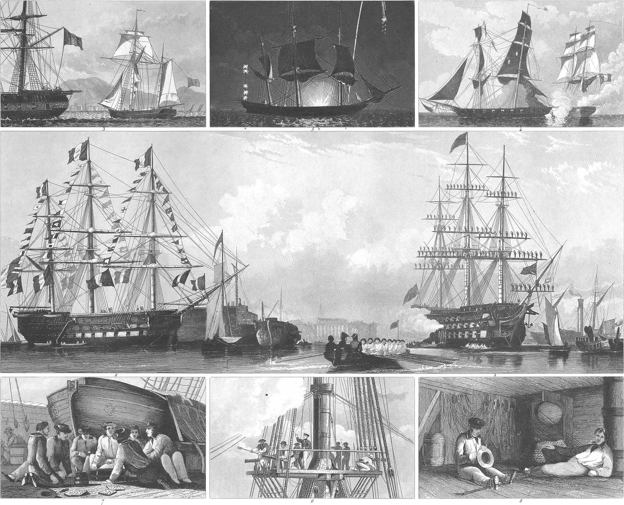
The vane (fig. 7) is very small and of different lengths. It is stretched at one end on a piece of wood, which turns on an iron spindle, showing the direction of the wind. Vanes are used chiefly by merchantmen. Ships of war carry not only their own flags, but those of other nations; and in war merchantmen do the same, in order to deceive the enemy. On coming into port, a ship displays its flag at the peak (pl. 25, fig. 3). A conquered ship of war surrenders by striking its flag (fig. 4). When a general salute is given all the sails are furled, the flags are displayed, and the sailors are paraded on the yards; at the same time a salute is fired by the cannon. Pl. 25, fig. 1, is an English ship of the line of 120 guns. On occasions of ceremony, the ships are dressed with flags. Fig. 2 is a French ship of the line of 120 guns. Flags are hung on all the masts, stays, shrouds, and other rigging. Etiquette is here observed in the disposition of the flags and pennants, the place of each being determined by the relation with the power which it represents. The flag of the royal house is placed at the head of the main-top-gallant-mast, and that of friendly powers at the heads of the fore and mizen-top-gallant-masts. The more unfriendly the relations with foreign states, the lower is the position of their flags. The least honorable place of all is over the cutwater. The flags in pl. 13 are designated by colors on the lower border of the plate.
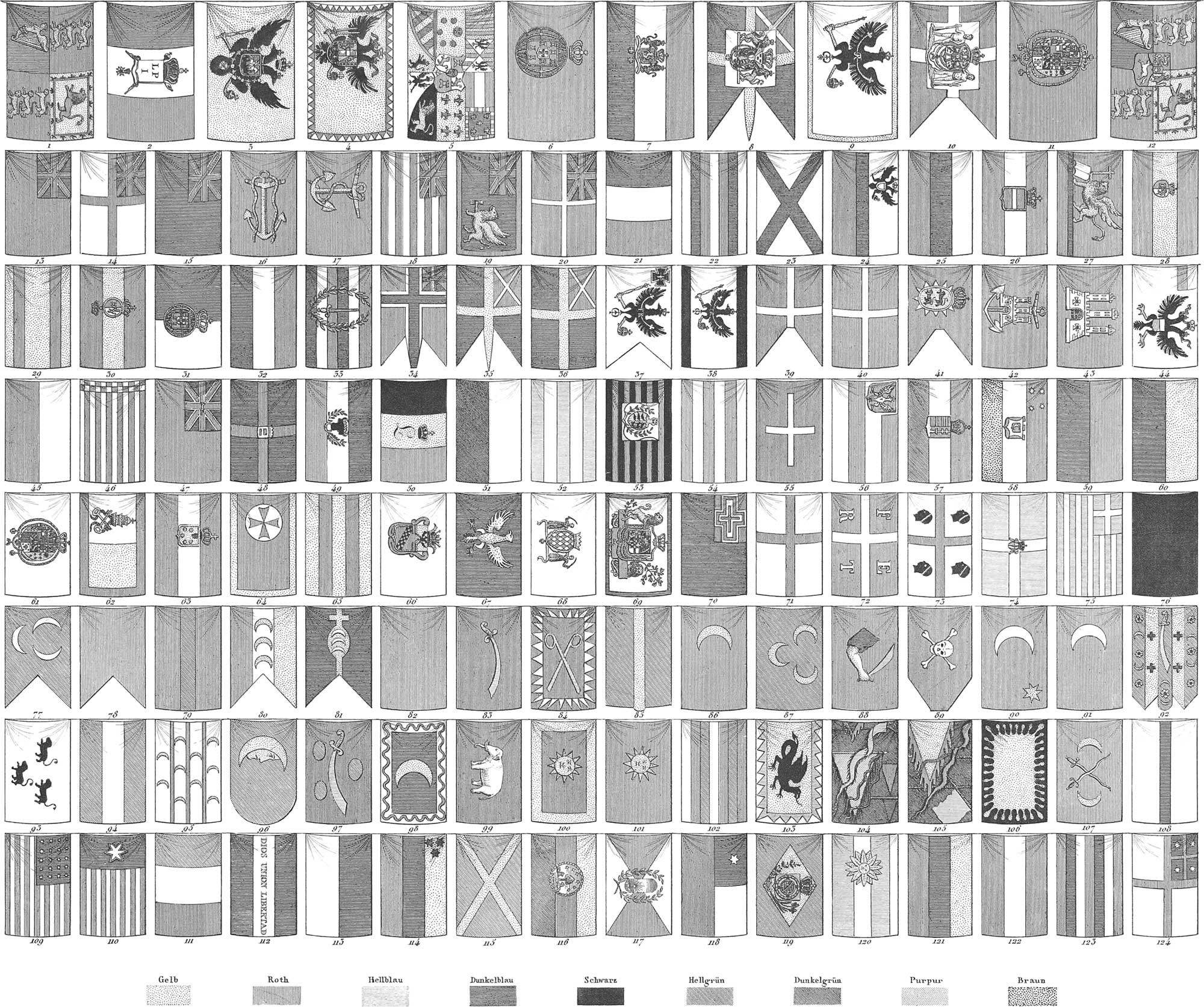
Glossary for plate 13
Given as an appendix to the explanation of the nature of flags and pennants. The colors of the flags are indicated by the different lines and dots marked at the foot of the plate: Gelb meaning yellow; Roth, red; Hellblau, light blue; Dunkelblau, dark blue; Schwarz, black; Hellgrün, light green; Dunkelgrün, dark green; Purpur, purple, Braun, brown.
Equipment of Ships
The equipment of a ship includes a great variety of articles which, though necessary to its service, are not comprised in its construction.
a. The Anchors. One of the most important parts of the equipment of a ship is the anchor, with its cable, serving to hold the ship in the same place, so that it can be moved neither by the wind, the waves, nor the tide. Pl. 10, figs. 14 to 29, shows a variety of different anchors and their separate parts. The anchor is a large iron instrument, which consists chiefly of a shank, and two arms which terminate in flukes. One of these (fig. 20), as soon as the anchor touches, strikes into the ground, and, by means of the cable connecting the ship with the anchor, the ship is held fast.
The parts of the anchor are the shank, A (fig. 19), the length of which, in proportion to its thickness, is as 18 or 16 to 1. The arms, DD, are two hooks which project in opposite directions from the lower end of the shank, called the crown, e (fig. 14). The flukes or palms are broad triangular pieces, pointed at the ends, which are forged into the extremities of the arms, and well adapted to take hold of the bottom. The ring, G, which passes through the eye, E, serves to hold the cable. The stock, A (fig. 18), consists of two beams of wood joined together by iron bands and rivets, inclosing the shank, B, below the ring, C, and standing at right angles to the plane of the arms. In constructing the anchor, the shank was formerly forged out of a single piece; later rods of iron were welded together (fig. 17, section); and finally it received the form as in C (fig. 16), the projections, a and b, being added, and the hole for the ring made at A. Places were arranged for the arms, which were forged separately, and then welded on. In this process three fires were necessary, one for the shank, and one for each arm; the forging was done on an anvil with an octagonal hole, through which the arms were passed in order to give the anchor the shape as in fig. 14. The piece, C (fig. 15), was added to the arm, B, and the fluke, A, to each arm. According to the modern fashion, the arms of the anchor have nearly a crescent form (fig. 19); the shank is forged of such a length, that it can be split and turned at H and B to each side, in order to form the upper surface of the arms; an iron wedge is then inserted at the crown, and a band laid on, which forms the lower surface of the arms, D. After all is welded together, the flukes, C, are attached. The stock serves to prevent the anchor from falling on the flat side, in which case the flukes would not sink into the ground, nor gain any hold. It also serves to turn the anchor if it falls flat, as the waves and the draught of the cable will turn the stock, which, being lighter than the water, and presenting a broad surface to it, will always remain partially floating, and the draught of the cable will then force the flukes into the ground.
The weight of the anchor is determined by the size of the ship. Each ship has several anchors. A ship of the line of 120 guns (pl. 11, fig. 1) has four anchors of 9000 pounds’ weight, one of 8000, two of 2700, one of 2500, and one of 1200. They all have their place at the forward part of the ship, partly on the outside. The sheet anchor is the heaviest, and is only used in case of a storm. A smaller sheet anchor is stowed on the lower deck and is only used on great emergencies. The next is the bow anchor, which lies on the larboard side of the bows. The stream anchor is on the starboard side. The hedges are used chiefly for warping a vessel from one place to another in a harbor or river. Besides these there are small anchors with three or four arms (pl. 10, fig. 26), called grapnels. Fig. 27 is Stuart’s grapnel. They are used to secure boats. There is another kind called grappling irons (fig. 28), used with a chain instead of a rope, and serving to grapple with an enemy’s vessel and for other purposes.
The different uses to which anchors are applied give rise to a variety of expressions. For example, when the anchorage is bad, a second anchor is connected with the first, this arrangement being termed backing the anchor (fig. 29). Of the two anchors with which a ship is moored, one is called the shore anchor and the other the sea anchor. We have also the flood or the ebb, the weather or the lee anchors, according to their position. In order to ascertain the exact place where the anchor lies, a rope is attached to the ring, before casting anchor, with a floating block of wood, called a buoy, at the other end. Pieces of cork (pl. 10, fig. 32) and casks (fig. 31) laid over with ropes are also used for buoys. A peculiar kind of anchor, called from its shape the mushroom anchor, is shown in fig. 33. It has neither arms nor flukes, but a trencher-formed foot, sharply curving upwards. It also has no stock, as the foot, A, is always ready to take hold, and is so heavy that the shank, B, never turns over to the ground. In harbors and roads, permanent anchors are used, to which the ships are fastened instead of casting their own anchors. The forked anchors (fig. 21) are used for this purpose. They consist of a short shank. A, with the ring, B, for the cable, and two parallel arms, C and C′. Fig. 22 is a shovel anchor, the shank of which has the stock, D, and the ring, C, at one end, and the broad, heavy shovel. A, at the other. The large hook-anchor (fig. 23) serves to hold several small vessels. It has the fluke D, with which it strikes deep into the ground, the knob A, and the holes B and C, for making fast the cable. The blocks (fig. 24 and fig. 25), the last with a notch for the fluke, are used to lay over the fluke after the anchor has been sunk, and to hold it down. To the cables of such permanent anchors are fastened large buoys, to which the vessels are moored.
The ropes for the anchors are called cables, and take their name from the anchors with which they are used, as the sheet-cables, bower-cables, stream-cables, and so forth. Besides these there are two spare cables. The cables are made of the same materials and in the same manner as the common ropes, and as they have to hold such a great burden often against an immense pressure, are constructed of an extraordinary thickness. They are composed of three smaller ropes, of three strands each, and sometimes of four ropes. They often have a hollow space in the centre, called the heart, filled with a light-spun rope. The thickness of the cable is half an inch for each foot of the ship’s breadth, consequently in pl. 11, fig. 1, 27\(\frac{1}{2}\) inches. The length is usually from 120 to 150 fathoms, and they are generally double the weight of the anchor to which they are attached. If a longer cable is used, it is made by splicing; two ropes together (pl. 10, fig. 30). [n the first half of the figure the splicing is finished, in the other the work is going on, the strands not being braided in. The cables for kedges are 125 fathoms in length, and often only 120. This last measure is called a cable’s length, and is used to measure short distances at sea. As the cable is not wound on the capstan or windlass, small ropes called messengers (pl. 11, fig. 15c) are attached to it, which pass round the windlass, and the cable is thus drawn in without bending.
Instead of hempen cables, chain cables are now extensively used. The ship, fig. 1, has two chain cables of 180 fathoms, four rope cables of 120 fathoms, two smaller ones of the same length, and two three-stranded hawsers also of the same length.
The Ship’s Boats. Every ship is provided with a number of boats of different sizes, which are used for such services as cannot be performed by the ship itself, on account of its size and weight or the shallowness of the water. The boats are distinguished from those in common use on inland rivers by not having broad and flat bottoms, but a sharp keel with side timbers arranged ship-fashion. An iron ring is attached to the stern and prow, to which is hung the tackle for hoisting or lowering. They are propelled by oars, but can also be fitted up with masts and sails. Each boat has from four to sixteen cross-benches, according to its size, for the rowers. Except those which are used to fasten the sails, and which are secured with iron bands, the benches are loose, and are removed to take in lading. At every bench are two thole-pins for the oars, called row-locks. The smaller boats are called yawls. The smaller merchantmen have only a long-boat, a yawl, and the captain’s gig or jolly boat. The sails are fore and aft sails (pl. 10, fig. 6), standing at two thirds the distance from the prow. A staysail is also sometimes used, and a jib rigged on a boom. The boats are used in heaving the anchor. The buoy rope of the anchor is passed through a pulley on the prow of the boat, and with a tackle hooked to the ring at the stern, is drawn in, or wound up by a small windlass on the bow, until the anchor is loose, when it is hove up by the capstan of the ship. The Portuguese and Spaniards have a kind of boat different from those in common use, which is sharper forward and broader in the stern. The yawl is lighter and narrower than the long boat, and when it is used with sails has two masts with spritsails (fig. 5). It is employed to bring the crew on board and for other light work. The captain’s gig is still lighter, and is built in an ornamental style. During the voyage the long-boat is kept on deck, over the main hatch, where it rests on boat-chocks. The yawl is placed in it. The captain’s gig hangs at the stern on the outside, on two davits fitted with tackles. Large men-of-war have six or eight or more boats and cutters of different kinds. Among them is the captain’s barge, or if there is an admiral the admiral’s barge, each with eight or ten oar benches. They are not the largest boats, but are built in a superior style. A man-of-war’s boats usually have fore and aft sails or spritsails, but are sometimes fully rigged, like a lugger or schooner. Pl. 4, fig. 7, is the cutter of a French frigate; fig. 8, the cutter of a French ship of the line; and fig. 9, the cutter of an English ship of the line.
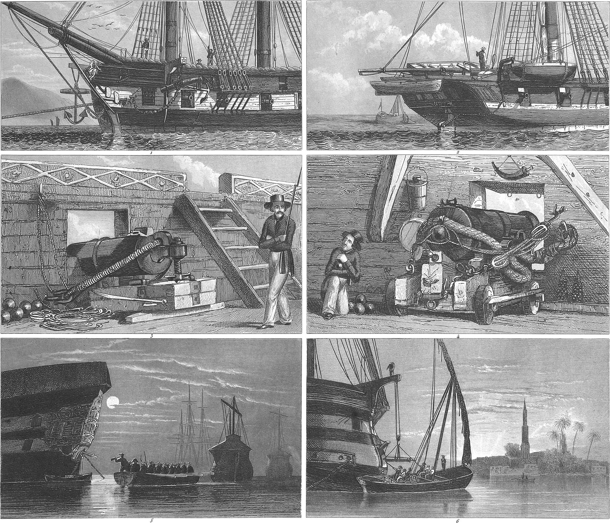
3. The Guns. All ships of war carry guns of greater or less weight; merchantmen, also, usually have two or three, and they should by all means have one at least for firing signals of distress. The heavy guns of a man-of-war consist of cannon, carronades, swivels, and mortars. The cannon are, for the most part, of a very heavy calibre. (In regard to the form of guns, the necessary information will be found in Military Sciences.) Those of the heaviest calibre are the most common. Large men-of-war have 36-pounders, 24-pounders, 18-pounders, and, rarely, 48-pounders; but recently 48- and 56-pounder Paixhans have been introduced. Although the guns of a ship are similar to those of the land artillery, their carriages are very different. Their form and construction are shown in pl. 21, figs. 4, 5, and pl. 22, figs. 3, 4. The carriages consist of two strong oak beams, called the cheeks, standing on two axle-trees with block-wheels, called trucks, of which the fore wheels are somewhat the higher. The cheeks are connected by a cross-piece which is cut out above, so that the muzzle of the gun can be lowered. The cheeks are held together by numerous key-bolts. A ring-bolt is attached to the outside of each cheek for the breech-rope of the cannon, and two eye-bolts for the side tackle. Grooves are cut in the upper part of the cheeks, to which the trunnions of the cannon are fastened with spring-bolts. The notches on the hind end of the cheeks serve as props for the handspikes when the cannon is to be pointed. At the centre of the hind axle-tree is an eye-bolt for the train tackle.
The gun-carriages in the French navy have a foundation frame consisting of two timbers, at the hind end of which is a ring to which the train-tackle is attached. The breech-rope does not pass through the ring-bolts in the cheeks, so that it can be laid back upon the breech of the gun, but through two holes in the cheeks. The French, moreover, use the standing-carriage, which has no wheels (pl. 22, fig. 3), but is made of two thick frames bolted together, and with grooves for the trunnions. The gun is pointed by means of a screw, instead of quoins. On the cheeks are two ring-bolts to which the breech-rope is fastened, thus greatly diminishing the recoil. In galleys, feluccas, gun-boats, and other small vessels, which are propelled by oars, the arrangement is different, as these can always be so turned as to bring the object fired at within range.
The weight of a ship’s guns and their carriages is as follows: iron 48- pounders, 9000 pounds; brass do., 7900 pounds; 36-pounders, 7450 and 6860 pounds; 24-pounders, 5382 and 4846. The carriage of a 48-pounder weighs 1500 pounds; of a 36-pounder, 1200 to 1300 pounds; of a 24-pounder, 900 to 1000 pounds; and of an 18-pounder, 740 to 800 pounds. A 48-pounder is served by 16 men; a 36-pounder by 14 men; a 24-pounder by 10 men; and an 18-pounder by 9 men.
The guns of a man-of-war usually project from the port-holes about two thirds of their length, the carriage touching the side, but in stormy weather they are drawn back and the port-holes are closed. This is more particularly the case with the guns of the lower deck. The guns are moved by different ropes: the breech-rope, the train-tackle, and the side-tackle. The breech-rope is a short rope, either laid around the breech of the gun or drawn through a hole in it, then drawn through the rings on the cheeks of the carriage, and hooked at the ends into strong rings on the ship’s side. It serves to prevent too great a recoil after the discharge of the gun, and also to keep it from rolling back when the wind beats the ship towards the opposite side. It must be long enough for the gun to be drawn so far back that its mouth will be two feet from the ship’s side, for the sake of loading it conveniently. When the cannon is in the port-hole, the breech-rope is laid upon both sides of it, and bound with cable yarn. The train-tackles (pl. 10, fig. 1 27) are used to draw the gun backwards. One of its blocks is fastened at the centre of the hind axle-tree, and the other to a ring attached to the deck. Guns of a large calibre have a double tackle (fig. 2 68). The side-tackle is used to draw the cannon to the ship’s side, and to project their muzzles through the port-holes. It is hooked to the rings of the two cheeks of the carriage, and to those on each side of the port-holes (pl. 22, fig. 4). For pointing and elevating the guns handspikes are used, and for the side direction, crow-bars with claws. If there are no elevating screws, two quoins are made use of When not in action, the guns must be securely fastened, as, if they get loose during the rolling of the ship, they do much damage, and may in some cases cause the loss of the vessel. In order to secure the heavy cannon on the lower deck, they are drawn back and the quoins taken out, which raises their muzzles to the upper part of the port-hole; a rope is placed round these, by which they are secured to a ring over the port-hole; the train tackles are hooked to the same ring, and to a strop which passes round the breech, and drawn taut; the side-ropes are also drawn taut, and the remaining part of them wound round the breech and through the ring on the ship’s side; they are then fastened together before the gun-carriage with another rope, and finally a wedge is placed under ihe hind wheels. A thick rope is also extended along the whole inner side of the ship through strong rings, which are on the deck between the guns, passing over the hooks on each side of the port-holes, and behind around the carriages, on which it is stretched taut at both ends.
The guns are shotted with a rammer (pl. 11, fig. 36), consisting of a stout rope’s end, with a swab at one end for sponging the gun, and at the other a thick wooden knob. There are also rammers and swabs with wooden stocks (pl. 11, fig. 33), and each in a separate piece; but those of ropes’ ends are more convenient. Figs. 37, 38 are the worms for extracting a ball from the cannon. The first is like that used for a musket; the second serves also to clean the barrel. The gun-ladle (fig. 39) is used when the cannon is loaded with loose powder instead of cartridges, to convey the powder to the butt-end of the barrel. The cartridges are woollen bags filled with powder, and often also containing a ball (see Military Pyrotechny). They are kept in a wooden chest on the deck, called the cartridge-chest. The ball is prevented from rolling forwards by wadding of tow or untwisted rope. The cartridges are pierced with a priming-wire, to enable the priming to reach the powder. This is contained in the powder-horn (fig. 45), which is borne by one of the men during an action, and is usually hung over the port-hole (pl. 22, fig. 4). Quick matches are often used in firing, and in that case the powder-horn is filled with pulverized gunpowder. When the guns are fitted with percussion locks the powder-horn is of course unnecessary, as well as the matches. The apron is a leaden plate placed over the vent of the loaded cannon, and is removed only at the moment of firing. Except during an engagement the vent is plugged up with tow, and the apron bound down upon it; when percussion locks are used, a case is placed over the lock instead of the apron. As the guns become very much heated by continued firing, a cooler filled with cold water stands by the side of each, to cool down the inside of the barrel with a swab, and the outside with a mop made of twisted ropes. An instrument called the visitor (pl. 11, fig. 40) is used to inspect the inside of the barrel; it consists of the rod, a, with a trigger and the ring, cc, which is attached to a second rod, b, over the first. If the instrument is pushed into the barrel without the ring the trigger springs into the cavity, if any exists; the ring is next inserted as far as possible without force, and then, without displacing the ring, the instrument is withdrawn, and thus the depth of the cavity may be ascertained.
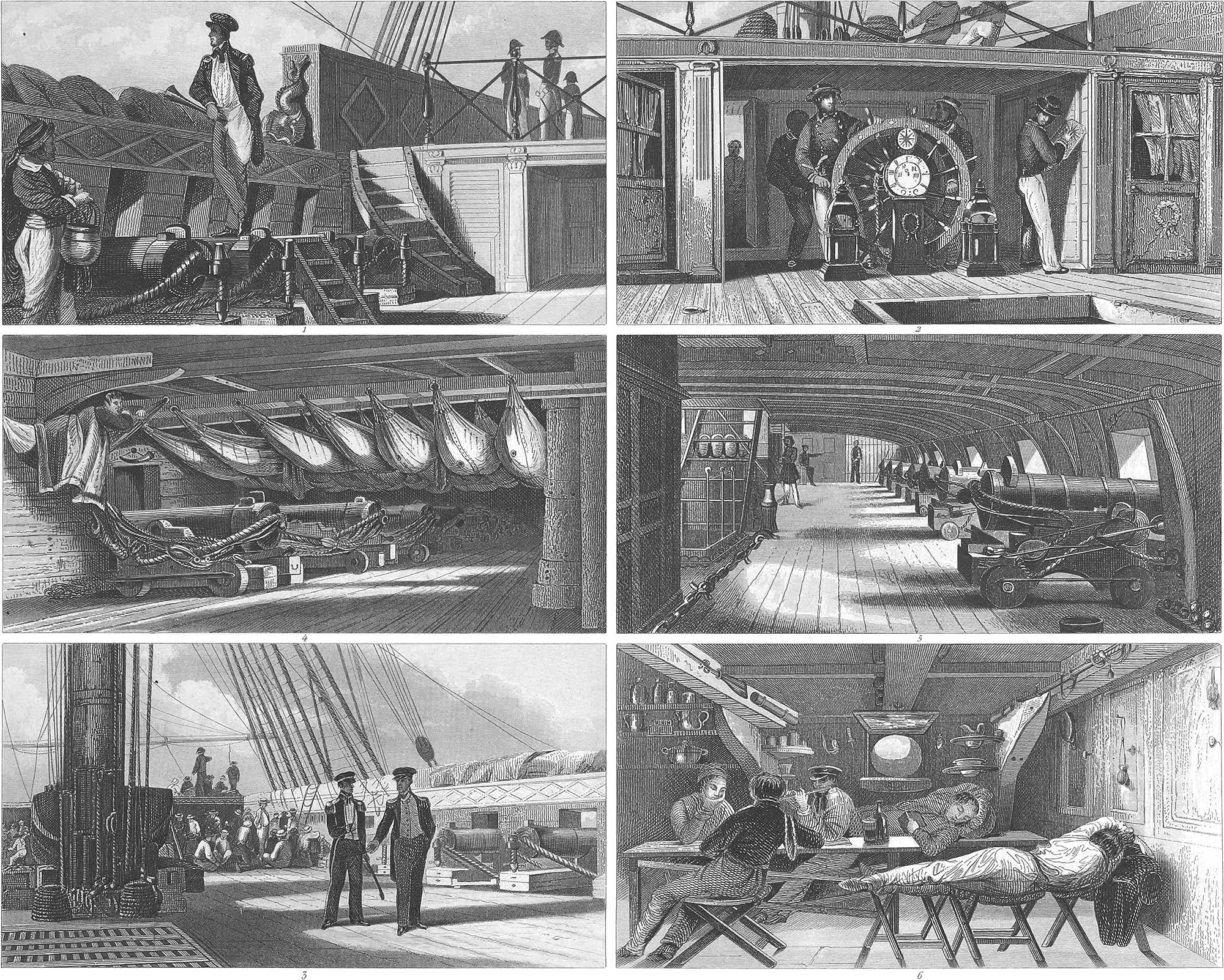
In shooting, balls are generally used in cannon; these are the most effective; canister shot and grape shot are also used for various purposes. The balls are kept partly in the shot-room near the pump-well, and partly on the shot-rack (pl. 21, fig. 5) formed of slips of wood on the right and left of the cannon. Canister-shot are small balls several of which are fired at the same time (see Military Pyrotechny). They are generally inclosed in bags of strong ticking, like grape-shot, with a circular wooden bottom (pl. 11, figs. 48, 49). Besides this kind of shot there are chain-shot (fig. 41b), bar-shot (fig. 41a), bolt-shot (fig. 42), club-shot (fig. 43), sliding-shot (fig. 44), which are intended chiefly to destroy the rigging and sails of the enemy; they are, however, little used, as, on account of their irregular shape, they cannot be fired with accuracy, and seldom hit the mark. Pl. 21, fig. 5, shows a starboard battery furnished with guns, as it appears when the ship is cleared in day-time; fig. 4 shows a starboard battery, at night, when the sailors are asleep in their hammocks, which in the daytime are stowed away in the netting (fig. 3, right hand above).
Carronades are a kind of ordnance which take their name from the Carron iron-works in Scotland, where they were first made. They were first used by the British navy in the revolutionary war with North America. The carronades have a chamber for the powder like mortars. They discharge larger shot than the common cannon, which are much longer and heavier, and carry further with a more certain aim. They are now used but seldom, as Paixhans’ mortars are far superior. (See Projectiles, in Military Sciences.) They are of various sizes and calibres. A 68-pounder weighs 3600 to 3900 pounds; a 44-pounder weighs 2227 pounds; a 32-pounder, 1714; and there are also 24-pounders, 18-pounders, and 12-pounders. Carronades (pl. 22, fig. 3) have a projection at the breech, through which a stout bolt passes, and on this the barrel is moved up and down. The breech tackle is rigged through a kind of ring in its upper part, and the direction given by means of a screw. The carriage turns with its frame upon a heavy bolt passing through the frame and the beam of the deck, and consequently carronades suffer no recoil, and do not require train-tackle or side-tackle. On account of the shortness of the tube, it can be loaded on the outside of the port-hole. Fig. 3 shows a carronade on the middle deck; pl. 21, fig. 1, is the aft starboard carronade battery, with the officer on duty. Fig. 3 shows the middle deck on the starboard side, with the main hatch, the long boat standing on the boat-chocks, the carronade battery, and the hammocks stowed in the nettings under the netting sails.
Swivels are small 1\(\frac{1}{2}\) to 2 pound cannon with a movable frame consisting of a thick wooden beam, to the upper part of which a pair of cheeks are attached, which support the trunnions of the gun. The beam passes through a round hole in a timber fastened on the ship’s side, and stands in an iron box on the deck. Small swivels are called swans’ necks, because they are hung to a strong curved iron fork. They are usually loaded with several musket balls and small shot. Blunderbusses are guns of a wide bore, which discharge grenades. Swans’-necks and blunderbusses are used on the tops. Other weapons are muskets, pistols, pikes, hangers, and pole-axes. Hangers are adapted both to cut and thrust; they are short, similar to cutlasses, and usually without a sheath. Pole-axes are like the common axe in front, but on the other side they have a stout point, three or four inches long (pl. 11, fig. 20).
Mortars are used on board ship for projectiles. These, with their blocks, have been already described under the head of Military Sciences. The mortars stand on the fore quarters of the upper deck; the deck beams must be strongly propped up for them, as they exercise a great downward pressure when they are discharged- Roding proposes that mortars should be placed on a strong floor of rope-work, the elasticity of which would diminish the pressure. The bombs which are thrown from mortars (fig. 46, view; fig. 47, section), are hollow iron balls filled with powder, with an opening on the top in which the wooden fuse filled with a slow match is placed. As soon as the mortar is discharged, the fuse takes fire, and continues to burn until the bomb falls. By that time it has kindled the charge of the bomb, which then explodes with great violence, destroying everything within its reach.
Men-of-war have great occasion for gunpowder, which, besides being used in action, is wanted for salutes and exercises, as well as for burning in the hold to purify the air. Merchant-ships also generally carry a considerable quantity of powder. In ships of war the powder is kept in a close apartment, called the magazine, of which ships of more than 60 guns have two. They are situated forward and aft, in the lowest part of the hold, and consequently deep under water, where they are usually safe from damage by cannon-balls and other accidents of the kind. They are separated by partitions from the other parts of the ship, the walls being often covered with sheet lead. They are lighted by a lantern, which stands in a basin lined with lead and filled with water. The sides are of horn and surrounded with a wire netting. The light is let in through an opening in the side. The powder is kept partly loose in kegs, and partly in cartridges and canisters. The door is constantly locked, and no one but the master-at-arms has the key. In merchant vessels the powder is kept in the run the after part of the hold, and is under the charge of the mate.
4. Provisioning the Ship. The provisioning of a ship, in regard to quantity, is determined by the number of its crew, the length of the voyage, the climate and productions of the country to which it is to sail, and also by its facilities for keeping its stores without injury. Delays during the voyage must always be taken into account, and consequently a supply of provisions must be secured for a longer time than the estimated length of the voyage. Even for the shortest voyage, provisions should be taken for not less than three months. Especially there must be a sufficient supply of fresh water, biscuit, dry vegetables, salt meat, and dried and salted fish. The quality of the provisions depends on the habits of the sailors. The English, for example, have fine wheaten biscuit, of excellent taste, while the biscuit of the Dutch is made of crushed rye, coarse and black as peat-turf; the English sailors are supplied with beer, butter, and plenty of meat; the Dutch, the Germans, and other northern nations, use a great deal of beer and butter and less meat, but, on the contrary, more flour and vegetables, as well as dried fish. Among the southern nations, wine is dealt out every day, but instead of butter they make use of anchovies, cheese, olive oil, and onions. The officers, both of men-of-war and merchantmen, have better fare, including poultry and milk, and also good wines and spirits. The fresh water is kept in large oaken casks with iron hoops standing in the hold. As fresh water is one of the prime necessaries of life and is very precious at sea, great care is taken for its preservation and economical expenditure. In men-of-war it is under the charge of an officer, and in merchantmen of the mate, who alone have the key of the water-room. The rest of the provisions are kept in sacks, chests, and barrels, and are under the charge of the steward. In merchantmen they are kept in the run, in care of the mate.
5. Other Necessaries on Shipboard. In men-of-war a special supply of provisions is laid in for the sick, as well as a store of medicines, surgical instruments, &c., under the charge of a head surgeon and several surgeon’s mates. A room with windows on the fore part of the upper deck is usually provided in English ships of the line for the reception of the sick, called the sick bay. Large fleets and squadrons have special hospital ships, for the accommodation of the sick whose diseases are dangerous. Merchantmen have no systematic arrangements for the sick, and only East India vessels and the largest packet ships carry a physician. But every captain has a small chest of medicines, with a book of directions for their use, and he thus takes the place of the physician in case of need.
In long voyages a supply of linen and clothing is taken in, in order to furnish the sailors, if necessary. This, however, depends on the pleasure of the captain, and, strictly speaking, does not belong to the equipment.
Among important parts of the equipment, we have finally to mention the various instruments and apparatus necessary to direct the course of the ship. The compass resembles the common surveyor’s compass, but is hung in a peculiar frame called gimbals, so that the needle and the circle of degrees shall always be as nearly horizontal as possible. The log (pl. 23, fig. 6) serves to measure the velocity of a vessel through the water. It is a three-cornered piece of board called the chip, to which the logline, running upon a reel, is attached by three legs, two of which are knotted through a hole in two corners, while the third draws out at pleasure. When the log is thrown into the water, it stands almost perpendicular, and at that moment a half-minute glass is turned. As soon as the glass has run out, the line, which is marked off into proportional spaces, called knots, and running freely, is suddenly stopped; the loose leg then draws out, and the log floats flat on the water, and presenting no further resistance is drawn on board; the number of knots is counted; and they each being in the same proportion to a mile that a half minute is to an hour (1–120), the velocity of the ship is easily determined. The lead is a heavy weight attached to a line, in order to measure the depth of the sea in certain places. When the lead is to be thrown (fig. 4), the ship is either hove to or her way is slacked, and three men standing on the chain-wales heave out the lead. When the line ceases to run, it shows that the bottom is reached, and the number of fathoms which the line has run off is then counted. There are also the quadrants and sextants, for taking the altitudes of the sun and stars, and ascertaining the longitude and latitude. With these are included the chronometers, some of which keep such good time that they lose scarcely a second in a voyage round the world. Charts, telescopes, barometers, speaking-trumpets, &c., are among the necessary articles. We may mention, finally, the different kinds of implements employed in various kinds of work on shipboard, such as the axe (pl. 11, fig. 19); the hatchet (fig. 25); the horse-bit (fig. 23), for cutting straight grooves: the adze (fig. 24), for cutting curved grooves; the scraper (fig. 21) and the double-scraper (fig. 22), to clean the planks and seams; the caulking-tools (figs. 26, 27), for driving in the oakum; the caulking mallets (figs. 31, 32, 32b); the pitch ladles (figs. 17, 18); the tar-brush (fig. 33); and the callipers (fig. 34), used to measure the circumference of the different spars and bolts.
The Different Kinds of Ships
In common parlance, every vessel that sails on the high seas, or perhaps only navigates a river, is called a ship; but seamen make nicer distinctions, and give that name only to vessels with three masts and square sails. It is not easy to divide vessels into exact classes, as the purposes for which they are intended, their size and construction, the arrangement of their masts and rigging, their armament, &c., establish differences, which are again set aside in particular cases by the combination of different qualities. The best method probably is to classify vessels according to the purposes for which they are designed, although in that case the same form will recur in different divisions.
In the external figure of a ship we distinguish the parts above water and those below water; the first are called the casing, the second the floor. The form of the floor is determined by the purpose of the ship. A ship of war must have the lowest guns at least four feet above the highest water-line; it must sail and steer well; it must carry numerous sails; it must not roll nor pitch much, nor make much lee-way. A merchantman must sail and steer well, carry many sails, lie easy on the water, contain a large cargo, and require only a small crew. It is difficult to unite these qualities, some of them demanding a broad, others a narrow vessel. Narrow vessels are rapid sailers; they make but little lee-way, but are contracted for room, and are apt to pitch Broad ships give more space, and if the keel is sharp and deep, can carry much heavier sail, as the masts can be made a foot higher for every inch in depth of the keel below the planking; but if the keel is flat, they pitch and make great lee- way. The English make the greatest breadth of the ship towards the bow, believing that in that case she sails better and minds the helm more readily; yet it has been shown by experiments in France that it is best to have the greatest breadth amid-ships.
The most important points in the construction of a ship are firmness and durability; all its parts, therefore, must not only possess the requisite soundness and strength, but must be so closely connected with each other, as to be able to resist the combined force of the sea and the wind.
The objects of the voyages, their duration, and the climate of the countries visited, have an influence on the size and construction of the vessel; we have, consequently, according to the size, ships of such a number of cannon; of so many tons; of the first, second, and third class, and the like; and according to the construction, frigates, cutters, galleys, &c., and steamboats. According to the objects of the voyages, we have ships of war, transport ships, merchant ships, slave ships, mail ships, privateers, and others.
Ships of War
The length of a ship of war is determined by taking the number of guns in the lower battery, adding the length of their port-holes (2 feet 11 inches for each 36-pounder) and the number of spaces between (7 feet 8 inches for 36-pounders), allowing two and a half of these spaces for the stern and prow, and we have the whole length of the ship from stem to stern. A ship carrying sixteen 32-pounders in each battery must consequently be about 187 feet in length. Although the spaces between the port-holes are sometimes less, the length of such a ship never falls short of 182 feet.
For the breadth of a ship (that is, the length of its main beam), some take the mean between a third and a fourth of its length, in this case 50 to 54 feet; others take 3 inches 3 lines to every foot of length, making the breadth from 48 feet 5 inches to 50 feet 6 inches.
The hold (the depth of the ship) goes from the lower side of the main beam to the upper part of the keel; it is larger at the stern than at the stem. In ships of war of forty-six or more guns, the depth of the hold is equal to half the breadth of the ship, and in frigates is somewhat greater.
For the angle of the stem-piece we take the eighth part of the ship’s length, and for that of the stern post \(\frac{1}{32}\) of the same dimension; that is, 22\(\frac{3}{4}\) to 20\(\frac{1}{8}\), and 5\(\frac{1}{2}\) to 6 feet. This determines the length of the keel. Ship-builders are not fully agreed on this point, however, some preferring to make the stem-piece almost perpendicular, and the stern-post wholly perpendicular. For the height of the stem-piece, some builders take one quarter of the ship’s length, others from one tenth to one twelfth, the stern-post being about one fortieth shorter.
The length of the main transom is two thirds of the ship’s breadth; it is placed at a height equal to the depth of hold and the elevation of the lower deck. No exact rules can be given for the form and position of the ship’s timbers. Vessels of a sharp build, in which the timbers make a large spring from the keel before bulging, draw more water than flat-built vessels, and hence present more resistance and make less lee-way. The latter, on the contrary, have less draught and are broader in the hold, which is an advantage in laying the lower gun-deck. The position of the main or middle timber, which determines the greatest breadth of the ship, is a controverted point among ship-builders, some placing it further forwards, and others near to the midships; the last is preferable, as it diminishes the burden towards the stern. The timbers at the stem and stern are drawn nearer to each other, contracting the hold in those parts of the ship: this is done at the stem in order that the ship may cut the water with more facility, and at the stern for the advantage of steering. The timbers are also somewhat contracted at the upper ends (forming the bulge of the ship’s sides) in order to break the force of the water and to bring the greatest burden below, to say nothing of other advantages. The breadth and the curve of the stern are according to the taste of the builder.
Ships of war are divided according to their size into classes, of which there are properly only three, the smaller vessels being called frigates, corvettes, brigs, cutters, sloops, &c. The English, however, reckon six classes, the Dutch seven, and the French five. In England, ships of the first class number 850 to 900 men, 100 to 130 guns, 178 to 200 feet in length, and 2000 to 3200 tons burden. They descend in proportion until we come to the sixth class, which have 150 to 200 men, 20 to 32 guns, 88 to 120 feet in length, and 400 to 680 tons burden. It is more common, however, to designate ships by the number of their guns. Ships which carry 64 guns and upwards are called ships of the line (pl. 25, fig. 2), because they form the line of battle in a naval action (pl. 29, fig. 3), and at sea always sail in a line before or abreast of each other. If they have three decks, they are called three-deckers; the others are called two-deckers. Pl. 14, fig. 5, is a French ship of the line of the second class. Frigates are the most rapid and easy sailers of all ships. Fig. 4 is a French frigate of 60 guns, and pl. 10, fig. 3, is one of the latest construction. The build of frigates and their outfit serve as models for ships of the line and other men-of-war, which are said to be frigate-built. In fact, two-deckers and three-deckers are nothing but frigates with one or two additional stories and larger masts, although their masts and sails are smaller in proportion than those of frigates.
The interior arrangement of ships of war differs in different countries, but it may be reduced to three principal methods, the English, the French, and the Dutch, as other countries merely copy one or the other of them, with more or less modifications. Ships of war of 90 or more guns are built with three decks, and those of 50 to 80 guns with two decks, besides those which are not furnished with guns or only partially. Frigates and smaller ships have only one gun-deck and no poop deck. The gun-decks are numbered from below, and are also called lower, middle, and main or upper decks. Each deck between the main deck and the hold is called a between-deck. The deck is divided lengthwise into the fore-deck, midships-deck, and after-deck. The lower deck carries the heaviest guns, in three-deckers mostly 36-pounders, and rarely 48-pounders or 56-pounders. The middle deck carries 24-pounders and 18-pounders, the main deck 12-pounders. On the fore-castle and quarter-deck are 6- and 8-pounders. Two-deckers have light guns throughout, from 24-pounders to 4- and 6-pounders. We will give a more detailed description of a Dutch and a French two-decker, as it is easy to apply the description to a three-decker or a frigate, by supposing one deck added or taken away. Pl. 9, fig. 27, represents the longitudinal section, and pl. 10, fig. 1, the upper view of the lower gun-deck; fig. 2, the view from above of the poop, the quarter-deck, the gangways, as well as the upper part of the middle deck of a Dutch two-decker of 74 guns. Although many parts of the main deck are concealed by the forecastle, the quarter-deck, and the poop, we have designated their place by numbers.
The hold, A (pl. 9, fig. 27), is the space between the keel and the lower gun-deck. It is divided into the lower hold and the upper hold, which are separated from each other by the orlop, a light deck near the water line. On this deck are the steps for the heel of the mizen-mast and for the gudgeon of the forward capstan 8′; the lower ends of the bitts 37 are also fastened here. The lower officers and mechanics have their berths on this deck, though they have no fixed position on it. The greater part of it is kept empty, in order to stow away articles on it during an engagement which would otherwise be in the way. The space below the orlop is, as it were, the cellar of the ship, and contains many rooms of various kinds. We here see the keel 1; it is altogether 140 feet long. The kelson, 2 parallel with the keel. Between these pass the ship’s timbers, which set into grooves in the kelson two inches deep. The spaces between them are filled with blocks called dead-wood. The kelson serves to support the heel of the masts and of the main capstan. The run, 3 where the ammunition is kept. The three bread-rooms 4 are lined with tin, for the better preservation of the biscuit. The after magazine 5 contains chests filled with cartridges and kegs of powder; and in order to lose no room, firewood is stowed in the vacant spaces. The room is lighted with the powder-lantern. 6 The after-hold 7 is floored with boards laid on the ballast, forming a sort of orlop, and contains barrels of beer, salt meat, and the like, the spaces being filled with firewood. The captain’s wine hold 8 is on the starboard side and is separated by a partition from the cheese-rooms 9 on the larboard. There are avenues running between the partitions and around and through them. The steward’s room, 11 where he keeps the provisions for daily use and distributes them to the galley and to the men. The water-cistern 12 is a vessel with a cock to supply the lower hold with fresh water, after the spoiled water has been pumped out. It is useful to the portion of the ship which remains under water to keep it full of water to a certain height on the inside. The pump well. 13 The shot-lockers 14 are places on each side of the pump well for keeping cannon balls. The cable-room 16 contains the cables, disposed in such a manner as not to disturb the equilibrium of the ship. The floor is grated for the water to drop from the ropes into the lower hold. The main-hold. 15 Orlops are erected here (as at 7) over the ballast. On these are placed the water-casks, over them the beer barrels, and then smaller barrels of provisions. The carpenter’s timber is stowed in this room. At about half the height of the room is an orlop with the berths of the sailing-master and of the boatswain and his mates. During an engagement the chests of the sailors are placed here, and are so arranged that the wounded can be laid upon them, while their wounds are dressed by the surgeon. This is called the cock-pit. The forward provision chests 17; the sailroom 18, where are kept all the spare sails, and when in port those belonging to daily use. Here also are passages 9 at the centre and the sides. In the middle one are hung the cartridge-boxes and powder-horns. Here is a second cistern 20 and a second magazine, 21 similar to the first. The forward run 22 is the most forward part of the hold, containing the spare ropes and rigging. A light is kept here day and night and a watchman.
The lower deck, also the first deck, B, carries fourteen 36-pounders on each side. The places between serve for the quarters of the sailors and marines, where their effects are kept, and where at night their hammocks are hung. Pl. 21, fig. 4, night time; fig. 5, day time. Pl. 10, fig. 1, and pl. 21, fig. 5, show the position and in part the fastening of the guns. The after part of the lower deck contains the room of the master-at-arms, 17′ pl. 9, fig. 27, extending from the stern almost to the mizen-mast, where it is separated by a thin partition covered with linen, which in time of action is removed. Here are the quarters of the midshipmen, the clerk, the surgeon, the chaplain, and others, and also, according to the room, some of the officers of marines. In this room, which is often partitioned off into several smaller rooms, we observe the tiller 15′ passing along the deck with the tiller rope, which runs on both sides and then back to the centre, going through each deck to the wheel, 41′ on the quarter-deck. The run hatch 19′ [25],1 where the master-at-arms keeps his stores. The bread room hatch 19′ [25]. The passage hatch 16′ [27], which, as the hatch to the after powder magazine is in the centre passage, is covered with lead and fastened with a padlock. The hatch to the steward’s room 14′ [28] leads to the wine hold, to the cheese room, and to the after lantern. The main capstan 13′ [29]. This shows also the mode of drawing in the cable by the messenger. This rope (pl. 11, fig. 15c) is from 9 to 12 inches thick, the ends connected together (as at bed), forming a ring. Knots, a, are made in it at the distance of every five feet. When the cable is to be hauled in, a few turns of the messenger are taken round the capstan, the remainder being stretched to the bow and attached to the cable near the knots by little flat ropes called nippers, with which the sailors take a few turns round both cable and messenger, keeping hold of the ends, walking along near the cable as it is wound on, and releasing the nipped cable when they have reached the hatchway (pl. 9, fig. 27 10′ [32]. The cable then descends into the hold whilst the messenger is being kept winding around the capstan, the unwound part, of course, returning to the bow, where the same operation is recommenced, and so on, until the whole cable is brought on board. The hatch to the after room 14″ [30] leads also to the after shot-locker and the cable room. On each side of the hatch are two stout rollers, on which the messenger runs. The pumps 12′ [31] discharge the water into gutters which carry it to the scuppers. The main hatch 10′ [32] leads into the main hold and serves to let down the barrels with which it is stowed. The blacksmith’s shop 9′ [33] with a small anvil, and a movable hearth with bellows. The floor is covered with sheet iron. The blacksmith’s shop is also often contiguous to the galley. The forward capstan 8′ [34]. The forward hatch 36 [35] leads into the forward part of the main hold. The sheet anchor is laid here, one arm of which reaches down the hatch. The bitts 37 [36], to which the cable is fastened. The hatch to the forward passages 36′ [37] and the hatch to the forward run 36″ [38]. The water troughs 21′ [39], which receive and lead off the water which comes into the ship when the anchor is hove up. The hawser holes 22′ [40], through which the cable passes.
The upper, or second deck, C. Although the poops, the quarter deck, and the forecastle are all over this deck, it is called the upper deck, because those parts are regarded as separate appendages. This deck, especially with the English, is now entirely built over, but as the erections have no broadsides of guns they do not receive the name of decks. The parts have the same names as before; the forward part is called the forecastle, the after part the quarter deck, and the passages on each side at the centre the gangways. In the deck here represented we find the cabin 23 [41], called the lower or main cabin. It resembles an elegant parlor, receiving its light through glass windows in the stern. In time of action, these are replaced by frames covered with fine painted wire. The port-holes on this part of the deck are also furnished with windows. On each side of the entrance to the cabin is a small room for keeping eatables and other stores.
The forward wall and the side partitions in general are movable and consist of lattice frames covered with linen, and are taken down on the commencement of an action. In English men-of-war these partitions are often of wood, but so constructed as to be easily removed. The cabin is finished in a style of great elegance and tastefully painted, and even the cannon have such a splendid exterior that one is tempted to regard them as martial ornaments. There is sometimes a difference in the arrangement, as after the upper cabin is finished the admiral or other high dignitary on board takes his choice, and the remaining one is partitioned off as quarters for the officers or their personal suite. The sleeping room of the commander-in-chief 24 [42], if he has his quarters in the main cabin, is between that and the second cabin. The church 25 [43] is a large room running across the deck, which is separated by a sail-cloth curtain from the poop and the other portions of the deck. Divine service is held in this room, and at the same time it is used as an armory and as a mess-room for the officers. A hatch to the lower deck 26 [44]. This is only made use of during a battle. The upper capstan 27 [45] serves as a support for the main capstan, with which it is connected. The stairs to the quarter deck 28 [46]. The after hatch 29 [47]. The main cross-pieces 30 [48]. When the ship is at sea, some spare spars are placed, one end on the cross-piece of the belaying pins and the other on the fore-castle, while other spars are laid crosswise with their ends on the gangways, forming a frame for the long boat and some of the cutters. The main hatch 31 [49], through which all barrels and other parts of the ship’s lading are lowered into the hold. A hatch with two ladders 32 [50], leading to the lower deck. The forward hatch 33 [51] is over that of the lower deck, so that each leads to the forward part of the hold. The caboose or galley 37′ [52] is a small room under the forecastle, containing apparatus for cooking, provided with a hearth, an oven, frying-pans, &c. The carpenter’s shop 42 [53] contains also the berths for the carpenter and his mates. The cook’s berth [54].
The quarter-deck, D, carries six 8-pounders on each side, and is the place where the officers, midshipmen, and sailors keep watch (pl. 21, fig. 1), The cabin in the after part (pl. 9, fig. 27 43) [55] is arranged like the lower cabin, but is superior to it in some respects. In addition to the side galleries it has also a stern gallery. From the cabin door the whole service of the ship can be seen at once. The cabin is lighted through a glass door in the after part and through the port-holes (42).
The deck over the cabin is called the poop-deck, from which two ladders (pl. 21, fig. 1, and pl. 10, fig. 2) lead to the quarter-deck. The signal-keepers are stationed on the poop-deck, with the chest of signal flags; the lead is thrown from the fore chain-wales, but hauled up and examined on the poop deck (pl. 23, fig. 4), and the nautical observations are here taken; it formerly carried cannon, but now it has only swivels. The deck runs from the taffrail to the mizen-mast, where it has a railing, which projects four or five feet over the cabin, resting there on posts.
Under this projection is the wheel (pl. 9, fig. 27 41) [56]. It is about nine feet in diameter, with an axle of fifteen inches (pl. 21, fig. 2).
The binnacle is before the wheel. This is a wooden box with three sliding partitions; in the middle division is a lamp hanging on gimbals, and in each of the contiguous divisions a compass, which is lighted by the lamp. Here also are kept the hour-glasses, the half-minute-glasses for the log, the spy-glasses, and the copper speaking-trumpets. No iron must be used about the binnacle.
The deck-light of the church 44 [58] is partly covered with a grating and partly with windows, forming a lantern with oblique sides; in rain and storms it is covered with a tarpaulin.
The accommodation-ladders 45 [61] are on the outside of the ship from the forward part of the quarter-deck to the surface of the water; they have ropes on each side, which, fastened at the top to iron bolts, serve as balusters.
The gangways 46 [62] on each side of the ship connect the quarter-deck with the forecastle.
The forecastle, E, carries three 8-pounders on each side. Two ladders 34 [63] lead from the after part of the forecastle to the main deck; between the forecastle and the main deck is the ship’s bell 35 [64], which is rung from the main deck; the chimneys 36 [65] of each galley have movable pots, to prevent the return of the smoke; the fore-cross-pieces 38 [66], for the running rigging of the fore-mast; the davits 39 [67], to hold the anchor when it is about to be cast, and to bring it up when it is hove; the kevels 40 [68] are stout cleats on the sides of the ship, for belaying the large ropes.
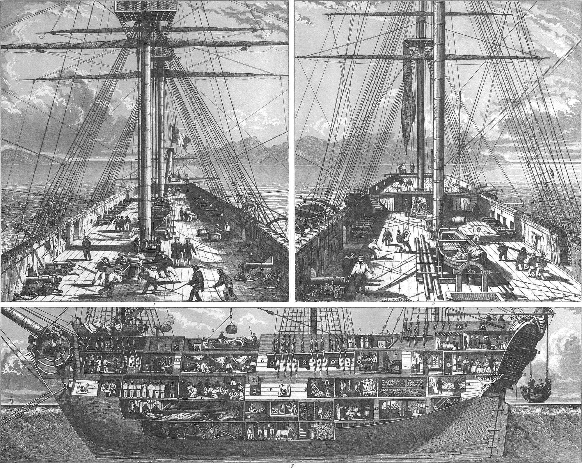
As we have described the Dutch ship of war at length, we need not enter into details with regard to the French ship, which is the same in all essential points, differing only in certain arrangements, which are shown in pl. 12. Fig. 1 is the main-forward-deck, fig. 2 the after-deck, and fig. 3 a lengthwise view of a French two-decker, with a portion of the planking removed. For the sake of still greater clearness, we have given on pl. 22, fig. 1, an external view of the forward part of a French frigate, fig. 2 the after part. We have only to add one story, and we have a two-decker. In pl. 12, figs. 1, 2, 3, A A are boats hanging at their scantlets; BB, the stern-galleries; C, the rudder; D, the poop; E, the hammocks; F, the first battery; G, the second battery; H, the third (half) battery; K, the davits, with the anchor; LL, the hawse holes, with the cables; N, the top; 1, sailors on the main top; 2, men drying the sails; 3, hoisting the signal flags; 4, tarring the bowsprit; 5, lowering the water-casks through the main hatch; 6, the surgeon examining the sick; 7, the captain’s cabin; 8, the dining-room; 9, the galley; 10, midshipmen’s cabin (see also pl. 21, fig. 6); 11, the sailors’ quarters; 12, drilling at the guns; 13, officers’ cabin; 14, officers’ mess-room; 15, hospital; 16, drilling the marines; 17, the sailors at dinner; 18, repairing the sails; 19, provision-room; 20, sick-room; 21, small boat; 22, sail and rigging-room; 23, prison (see also pl. 25, fig. 8); 24, shot and rigging-room; 25, wine and spirits-room; 26, powder magazine; 27, tackle-room; 28, general store-room; 29, cattle-stalls; 30, fodder-room.
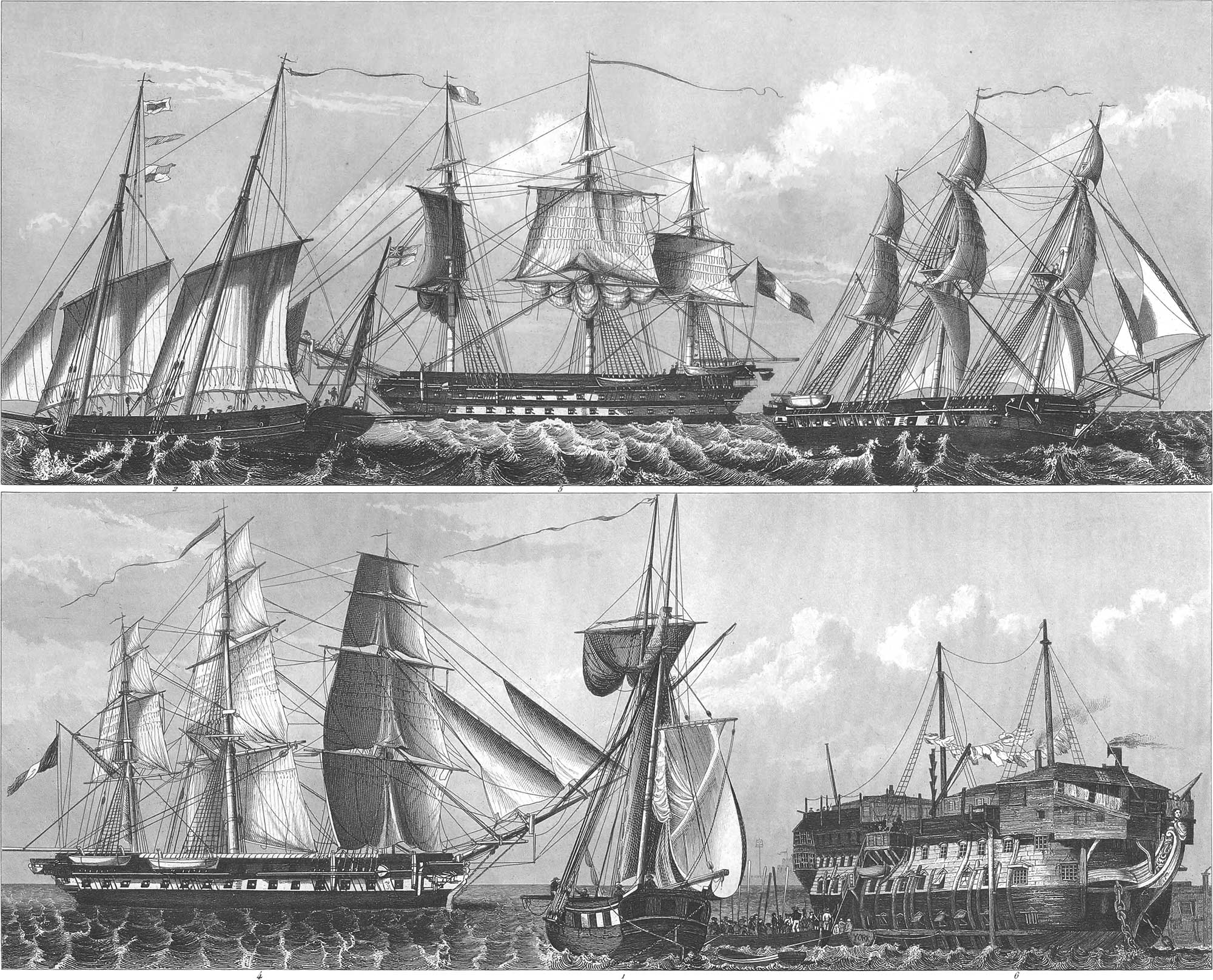
Frigates (pl. 14, fig. 4, and pl. 10, fig. 3) take the first rank after ships of the line, and are built on a similar plan. They have three masts, with the same kind of sails, quarter-galleries and head, with forecastle and quarter-deck, but no poop, and only one gun-deck. They formerly carried as many guns on the forecastle and quarter-deck as on the main-deck, but now they are made longer in preference, in order to have the cannon mostly in one battery. There are frigates of from twenty to sixty guns; those with over thirty are called heavy frigates. Frigates must sail rapidly and near the wind, but at the same time be able to bear the sea in a strong wind, as they are used chiefly as cruisers, sailing in all directions to watch the motions of the enemy, to clear the sea, to convoy merchantmen in time of war, or to bring prizes into port. In a general engagement they take no direct part, as they could not stand long against a ship of the line. They consequently take position behind the line, and form a second row, protecting the transport and hospital ships, and coming to the aid of the ships of the line at the orders of the admiral. Some of them are deputed merely to communicate signals from the admiral’s ship during the battle, and are hence called repeating frigates. After an engagement the frigates take in tow those ships of the line which are so disabled that they cannot sail, and, in short, they perform an endless variety of duties, and may be called the light troops of the sea service.
Next to the frigates come sloops-of-war, also three-masted, but sometimes with only two masts, built like frigates, and carrying only from fourteen to eighteen guns. The two-masters have only the main-mast and the fore-mast, each of them somewhat longer in proportion than those of frigates, in order to supply the place of the mizen-mast. The try-sail is attached to the main-mast by a gaff; it is broader at the foot than at the head, and is stretched by a sheet. Instead of the main-mast it is sometimes hung to the snow-mast, a spar fastened between the trestle-trees, and is hence called a snow-sail. Merchantmen with masts of this kind are called snows. Sloops of war are very easy and rapid sailers; they are used to convey orders, for cruising, and for blockading harbors in which there are no ships of war. Pl. 14, fig. 3, is a three-masted sloop of war, frigate built, of twenty-two guns.
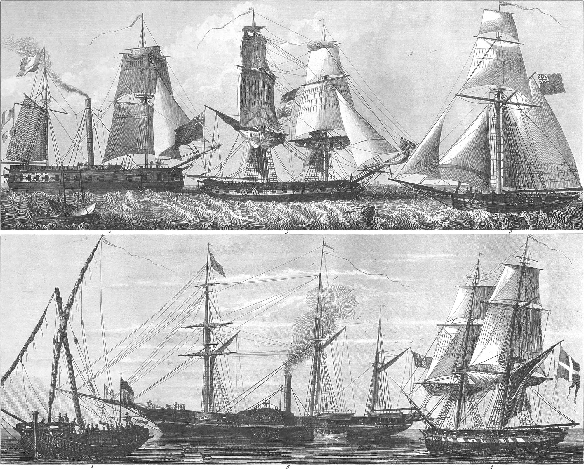
A brig or brigantine closely resembles a two-masted sloop, for which it is often mistaken. The difference consists in the mizen-sail, which in a brig is not a gaff-sail but a boom-sail (pl. 10, fig. 6), attached by a boom to the main-mast. As the boom projects over the stern, and must be turned, there is no flag-staff, and the flag is drawn up by the flag line to the gaff-arm, an arrangement prevailing in all vessels which have boom-sails. A brig has no forecastle or poop-deck; it has from fourteen to twenty-two guns. Pl. 17, fig. 4, is a Swedish 20-gun brig of war, sailing close to the wind; fig. 5, an English 20-gun brig, laid-to. The object of this manœuvre is to deaden the ship’s course in an instant, and it is performed by bringing one half of the sail to the wind, and bracing the others aback. Two signal flags are flying at the fore topsail yard-arm in our figure.
Cutters, another kind of vessel of war, have an entirely different build, and are adapted to make their way through the water with the utmost rapidity. They are rather long; the stern is small, and sits deep in the water; the prow stands perpendicular, and has no head. A cutter at the most is 100 feet long, 32 feet wide, and eighteen feet deep, of 180 to 360 tons burden, and carrying from 6 to 8 light guns, usually G- or 8-pounders; they have only one mast, very high and inclining towards the stern. In small cutters the mast is of one piece; in those of a larger size there is a top-mast and cross-trees, but no top; the bowsprit lies horizontally. A cutter has a boom-sail, a top-sail, a top-gallant-sail, several stay-sails, and sometimes also a royal; a studding-sail and a spanker may also be used. They are employed as coast guards, and to carry orders. Pl. 17, fig. 3, shows an English war cutter close to the wind. The cutters in the merchant service must carry other sails. A smaller kind of cutter carries from four to eight light guns.
Schooners are built like cutters, but have two masts. The fore-mast carries a gaff-sail, and the main-mast a boom-sail of considerable height. Both masts have stay-sails, and also top-gallant-sails. There are several stay-sails on the bowsprit, and a fore-stay-sail on the fore-mast. As the stay-sails have no effect when the vessel is directly before the wind, a square fore-sail is then set, which in such cases is also used in sloops and cutters. A schooner carries from four to eight light guns. A variety of manœuvres by these vessels is shown on pl. 29, fig. 1.
A galliot is a medium between the brig and the schooner, which is now in common use in the navy of some countries. Its sails are adapted to take the greatest advantage of the wind, and this circumstance, as well as the great simplicity of the rigging, makes it a favorite when light guns are to be used, and when the burden is under four hundred tons. They generally carry from ten to twenty light guns, and are built in every variety of fashion. The common galliot has a yard on the main-mast, and also on the fore-mast. The brig-galliot has on the fore-mast the fore-yard, fore topsail yard, and fore topgallant-sail yard like a brig, but its main-mast is galliot-rigged. Both masts have boom-sails, and the fore-mast has two stay-sails. Pl. 16, fig. 2, is a Dutch brig-galliot, drying sail. There is sometimes also a royal (pl. 15, fig. 9). Pl. 14, fig. 1, shows one galliot with only a yard at the fore-mast.
A lugger is a small vessel used for carrying orders and the like. It has two masts with topmasts standing in iron rings. The four sails carried on these masts are fastened to yards. The bowsprit can be extended at pleasure, and carry two or three stay-sails. A short mast stands on the stern, serving also as a flagstaff, to which a spanker can be attached. Fig. 3 is an English lugger giving signals.
We must also here make mention of galleys, although they properly belong to the middle ages. They are still used to some extent in France, Spain, and Portugal, and the coast guard of Sweden consists of a kind of small half galleys. The galleys alluded to in the public journals are properly nothing but ships of war which have become unfit for sea service, and being unrigged are used for prison-ships (pl. 14, fig. 6). Similar to the galleys, but smaller, are the feluccas, used in the Mediterranean Sea (pl. 4, fig. 11, is a felucca drawn up on the land), which are usually 52 feet long and 12 feet broad. They are used both with sails and oars. They serve for the most part as coasters, and are furnished only with some very light guns or with several swivels. Usually they have 12 rowers on each side. The feluccas have two masts, projecting forward from 3° to 5° and carrying lateen sails. There are twelve openings on the deck for the rowers, who do not sit on benches but on the inclosures around these openings, and resting their feet on blocks inside the gunwale. The planks which form the sides project at the stern, and are connected by a board bearing the name of the craft. The helmsman sits at the end of this extension, as the tiller turns on the outside, on account of the captain’s tent which occupies the stern.
Xebecs (pl. 15, fig. 5), used in the Mediterranean, are long, narrow, and sharp-built vessels, serving principally as cruisers. The smallest xebecs have 12 guns, and the largest 40. They carry three masts; the fore-mast inclines forward, and the mizen-mast has a small yard, to which a square sail can be attached. The masts have no topmasts, but only shrouds, and carry lateen sails. The gaff is composed of two pieces and is longer than the mast tree. The rigging for the sails is very simple, yet these vessels sail with great rapidity. The prow forms a projecting beak, which takes the place of the bowsprit. The stern also projects and has a tent for the captain.
Gunboats are built in a different fashion in almost every country. They have all, however, strong, flat bottoms, as they must keep close to the land, in order to attack fortified places, to convoy coasters, or to land troops. Although they can present no resistance to large ships of war on the open sea, they can give them great annoyance near the shore, as they can run in and out of places which the ship cannot enter, on account of the greater draught. The small boats almost always hit the ship, while she usually fires over them. They seldom carry more than 4 or 6 guns, which fire from the bow and the stern; they have only one mast, with a boom sail or gaff sail and a stay-sail; pl. 17, fig. 1, shows a Spanish balancella converted into a gunboat.
Bomb ketches are vessels of medium size, carrying two mortars on the bow in order to bombard cities and harbors. They must often operate near the shore, and are consequently built with broad and rather flat bottoms and with great strength (pl. 4, fig. 10), in order to bear the recoil of the mortars. They carry a main-mast and a mizen-mast, with yard-sails and stay-sails. The fore-stay-sails are very large in proportion to the others, as the main-mast to which they are attached stands aft of midships in order to give room to the battery on the bow. When the mortars are to be discharged, all the rigging is taken down from the mast, and only the fore-stay remains in its place, and it is, therefore, made of iron. Besides the mortars, the bomb-ketches each carry 8 light guns aft of the main-mast. The English also have three-masted bomb-ships and the so called kits for the same purpose, with a main-mast and mizen-mast, yard sails and stay-sails, and also gaff sails and jibs.
The fire ships, which are used to burn the vessels of an enemy, have no peculiar construction, but are old vessels no longer fit for sailing, which are entirely filled inside with pitch, sulphur, gunpowder, and other combustible materials, the rigging being also covered with tar, or sulphur and pitch united together. Everything is connected by trains of gunpowder, so that as soon as the priming is kindled the whole vessel is instantly on fire. When a fire-ship is to be attached to a vessel, it is brought to the wind-ward side; grappling-irons are fastened on the yards in order to catch into the enemy’s rigging; they are also thrown upon his decks and their chains drawn tight; the priming is then kindled, and the men make their escape. Instead of fire-ships, Congreve rockets are now generally used. (See Military Pyrotechny.)
Among ships of war are also included war steamers, which we will pass over for the present, as we shall devote a section to steam-vessels, in which we shall recur to the use of the steam-engine in men-of-war. We must here, however, consider one or two other kinds of vessels, which are not, indeed, directly ships of war, as they carry no guns, but are still made use of in naval warfare.
Among these are transport ships, used for carrying troops, horses, and other munitions of war from one port to another, or to the stations of men-of-war. Every fleet has a number of these ships attached to it, which carry a supply of sails, rigging, powder and ball, provisions, &c., in order to make good any deficiency. Transports are built frigate-fashion, but are not equipped as men-of-war. During an action they are stationed in the rear of the line, at a distance. They, however, sometimes have a certain number of guns and men, so that at least they can defend themselves if attacked by smaller vessels. The interiors of these vessels are constructed in different modes, according to the purposes for which they are intended, either to transport troops, horses, luggage, freight, artillery, or provisions.
Hospital-ships are generally old frigates or ships of the line past service, the decks of which are converted into wards of different sizes for the sick, and rooms for the physicians, surgeons, and nurses, together with an apothecary’s shop. Each division of the fleet has one or more hospital-ships, as only patients with a slight sickness are kept on board the man-of-war and the wounded only receive their first dressings in the cock-pit.
Prison-ships have the same general arrangement, though the rooms used for the confinement of prisoners are smaller and stronger, and there are also rooms for work and for religious service. The overseers and officers have their quarters in the cabin. There are also prison-ships in harbors, and these are entirely unrigged and covered in. Pl. 14, fig. 6, is an English ship of the line of the first class, unrigged, and converted into a prison-ship. It might also be used as an hospital-ship.
Privateers are men-of-war of every description, not exceeding light frigates in size. They are fitted out in time of war by private persons, in order to attack the enemy’s merchantmen and to destroy his commerce. They receive a commission, called a letter of marque, from the government, with which they share their prizes. The vessel captured must be brought into a port and there condemned by the court of admiralty, before the privateer can claim her as his property. Privateers should be swift sailers, in order to overtake their prizes and to escape the enemy’s cruisers. Schooners, luggers, and brigs are employed as privateers, but their masts and sails are larger in proportion than those of other ships of war, and in a calm they also make use of oars, which pass through small openings between the port-holes.
Merchant Vessels
Those vessels which are built exclusively for the merchant service are called merchantmen. The guns which they usually carry are so light that they need not be taken into account. It is the main object in merchant vessels to gain an abundance of stowage-room for the freight, together with the necessary accommodations for the crew, which we may add should be as small in number as possible. The spare rigging and sails are mostly kept in the forward part of the vessel, as this space is so much occupied by the fore-mast and windlass bitts that it is not adapted to the stowage of freight. The different parts of the merchant vessel are less exact in their proportions than in ships of war, and their construction often varies essentially in the same country. The smaller vessels do not compare with the larger ones ia swiftness of sailing, though they are more pliable. They can, indeed, be built to sail as well as the larger ones, but in that case they must be built broader in proportion, in order to carry more sail, consequently they require a larger crew, so that the advantage is again lost. We have just stated the properties of a good merchantman. In order to secure these it must be very broad in proportion to its length, deep in the hold, and with a flat bottom; but then it will not sail rapidly, nor close to the wind, and the less as it is laden heavily and has a great depth of draught. For a ship to sail well, close to the wind, making small leeway, and easily managed in a rough sea, it must be able to take on much sail, and consequently must be stiff in the timbers; it must be of good breadth of beam, with a sharp bottom, and on account of the large sails and anchors in that case, must be manned with a numerous crew. If a small crew is to be employed, the vessel must have small sails and anchors, and hence must be of a narrow build; but it can then carry little freight. These various qualities, it is evident, are for the most part inconsistent with each other, and on that account the main proportions of merchantmen differ, according as they are designed for different objects.
The burden of merchantmen is measured by tons. A ton weight is equal to 20 cwt. dead weight. But as both capacity of carriage with regard to weight and room for stowage have to be taken into consideration, the ship is usually measured by the latter, and a ton of measurement is equal to 40 cubic feet, by which standard light goods are shipped, whilst dead weight, with which the ship cannot be fully laden without sinking, is reckoned by tons’ weight, according to the ship’s capacity of burden.
There is a great variety in the kinds of merchantmen, but they are all more simple in their construction than ships of war. Those of the largest size have a deck below the main deck, called the between-deck, in the forward part of which is the cable-room, where the cables and the spare rigging are kept. The cabin, which is usually furnished with considerable elegance, is at the stern. This contains the sleeping berths for the captain and mates. In the run, under the cabin, is a sail-room, where the sails are kept, and the steward’s room, for provisions. In merchant vessels the galley (kitchen) is on the deck, abaft the fore-mast or between the main and fore hatches. The crew have their berths under the forecastle. When the forward hold of the ship is divided off by a partition, the space is called the forward run, and serves as a store-room for fresh water, firewood, coal, &c. Vessels of a smaller size have no between-deck, and the whole interior space is occupied for stowage, except a small portion at the stern, which is partitioned off for the cabin. For the crew and luggage there is a place constructed on the deck abaft the main-mast, containing the galley, the steward’s room, and the sailors’ berths. The cables and spare rigging are kept on the deck, covered with tarpaulin. As regards the external construction and rigging, merchantmen are classified as ships, barques, brigs, schooners, sloops, cutters, lucrorers, &c.

Full-rigged ships have three masts with square sails. They are of sharp construction, with a head and sometimes galleries. Pl. 26, figs. 9 a b, represent French ships of this kind under sail. Pl. 15, fig. 1, shows the after part of a French merchantman, with a shark being drawn in at the stern. Vessels of this kind measure from 300 to 1000 tons, and sometimes more. The East Indiamen, intended for long voyages, carry 8 or 10 small guns on each side of the between deck. In the middle of this deck places are partitioned off for the sails, the spare rigging, and the ship’s stores. The spaces between the guns form the quarters of the crew, who often number from 80 to 100 men. The galley is forward in the bow. The cabin is often splendidly fitted up.
Brigs (pl. 15, fig. 11) are very favorite merchant vessels, as they have two masts with square sails and can be managed by few men.
Pinks (pl. 15, fig. 6) are used principally in the Mediterranean, though less common now than formerly. They have three masts, the two forward ones being made out of one piece. They have lateen sails. A projecting beak takes the place of the bowsprit. The sails are awkwardly arranged. In a high wind square sails must be hoisted, in order that the vessel may stand the sea. The fore-mast is particularly inconvenient, as it inclines forward to an excessive degree. In the North Sea and the Baltic the name pink is applied to three-masted merchantmen, which differ from barks only in being higher built, sharper below, and narrower in the stern.
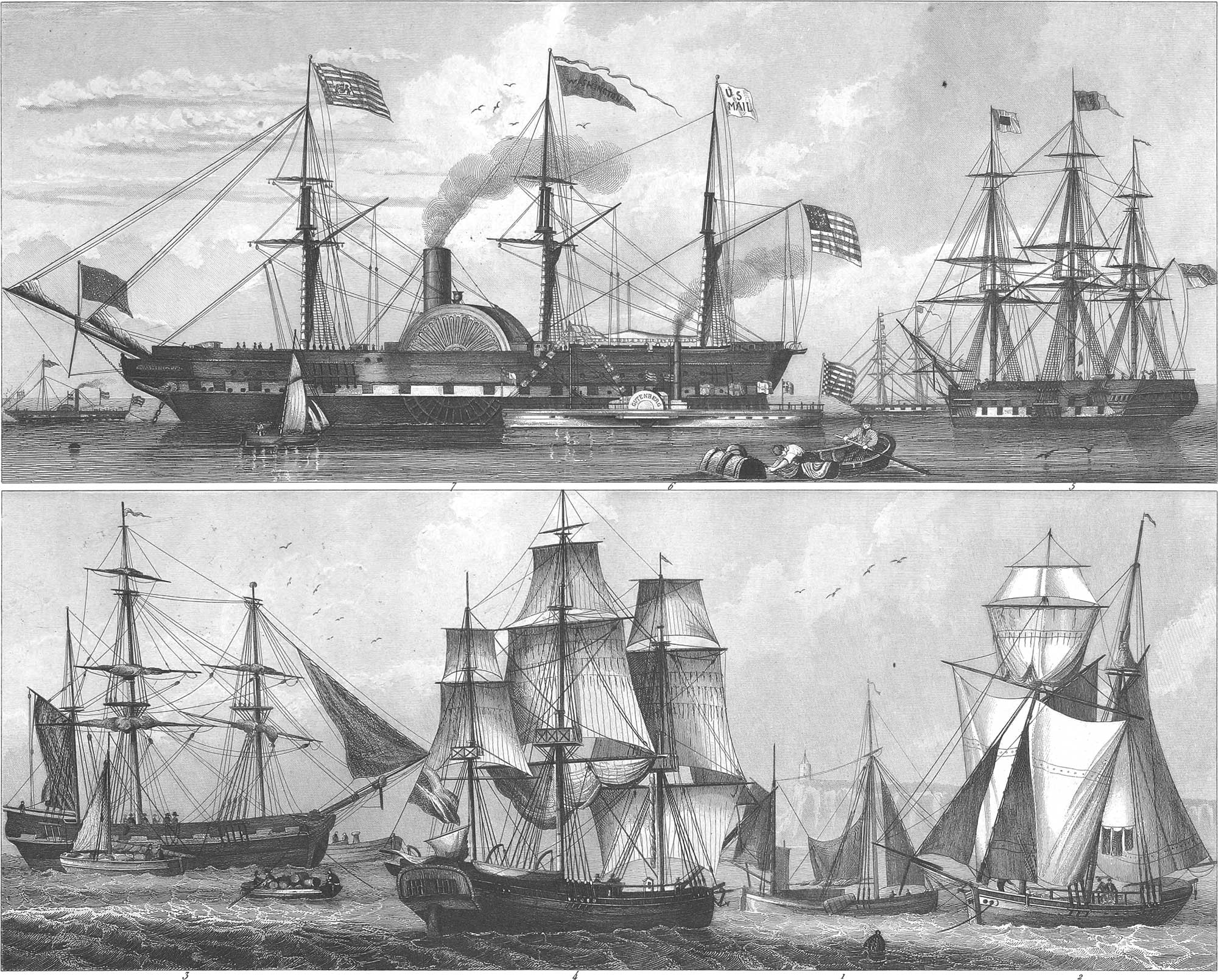
Barques are three-masters, square-rigged on the fore and main masts, but with gaff-sails on the mizen. Fig. 10 represents a barque with her sails loose; pl. 16, fig. 4, one at anchor, taking in freight. By a barque in the Mediterranean is understood a short, full-built ship, with the greatest breadth forward. The main-mast is in one piece, but high, and fitted with a main-sail, a top-sail, and a stay-sail; the mizen-mast is in the common form, with top-mast and top-sail. The fore-mast inclines forward and carries a lateen-sail. A beak takes the place of the bowsprit.
Galliots are two-masted. They carry masts and sails like brigs, only the fore-mast is the highest. Fig. 8 shows a galliot under sail.
Howkers, when they are three- or two-masters, are similar to the galliots, but have a head forward. They usually carry a main-mast and a mizen-mast. They have a main-sail, and often a top-sail and top-gallant-sail. There is a fore-stay forward with a jib, and often a flying-jib on the jib-boom. These vessels are in use among the Dutch, the Danes, and the Swedes.
Cutters are rather flat, round at stem and stern, and have a main-mast and mizen-mast (pl. 16, fig. 1). The mizen-mast, and sometimes also the main-mast, carries a gaff-sail with a bonnet, which in good weather is laced to the lower part of the sail, in order to increase its area. They are virtually only two-masted sail-boats.
A kind of vessel, called a tub, is used in the North Sea and the Baltic, fitted with lee-boards, in order to prevent too great lee-way with a side wind. These lee-boards are made of thick planks plated with iron, with about twice the length of the vessel’s depth, and the breadth equal to half the length. They are in the shape of a butterfly’s wing. They are attached to the sides of the vessel, where they turn on a head-bolt, and when in use hang like a sword on the side. There is one on each side of the ship, and when it sails near the wind, the lee-board is hung perpendicularly in the water on the lee-side, enabling the ship to make more resistance to the wind and thus diminishing the lee-way. When their use is no longer required, they are drawn back by a tackle to the sides of the ship.
Schooners have two masts, with gaff-, boom-, and stay-sails. If they carry a sail between the mast-head and the gaff, they are called topsail schooners.
Hermaphrodite brigs (pl. 16, fig. 2) are two-masted vessels, brig-rigged forward and topsail-schooner-rigged abaft.
Ships for Special Purposes
Certain vessels, which, strictly speaking, belong to the class of merchantmen, are yet built for special purposes, and consequently have a peculiar construction, sometimes in the exterior but always in the interior.
Among these we may reckon the fishermen, merchant vessels, but provided with the necessary apparatus, boats, and other arrangements for fishing. Whale-ships (fig. 4) are built for the pursuit of whales in the Northern Ocean, the South Sea, and on the north-west coast of the Pacific. They are usually three-masters, and built with great strength, in order to resist the ice. They are well supplied with spare boats as a provision against the numerous casualties to which they are exposed.
Large three-masters, called flutes, are built in Holland and Hamburg for the whale fishery, round at stem and stern, and very flat throughout. The masts are short in proportion, and the ships sail too slow for merchantmen. In the South Sea, as it is a great distance to the fisheries, fast-sailing vessels are used, carrying presses and kettles, in order to press out the blubber on the spot. For the herring fishery a kind of vessel is used called a buss, which has a main-mast with a main-sail, a top-sail, a stay-sail, and a mizen-mast with a half mizen-sail. The nets for taking the herring are dragged by the ship, and when filled are brought in by the windlass.
Coasting vessels are used for the coast fisheries as well as for the coasting trade, for which latter purpose they are built lighter, and rigged for rapid sailing. For the fisheries they are built heavier, in order to stand a rough sea. Pl. 15, fig. 4, is a French coaster fitted out as a fisherman. Smaller vessels are called fishing-smacks. Fig. 2 is a Havre de Grace vessel of this kind. Fig. 3 is a vessel used in the Mediterranean as a coaster, and sometimes for longer freighting voyages, as they are of a good size and are well rigged. Pl. 11, fig. 2, is the forward part of a Normandy fishing-smack. Pl. 15, fig. 1, is a Newfoundland fisherman.
Slave ships (fig. 11) are vessels which purchase slaves on the coast of Africa in order to sell them again in other parts of the world, especially in the West Indies and South America. They are usually brigs and schooners; they must be fast sailers, and therefore have large masts and sails. They must also be of a broad build, for the sake of room in the hold. As much has been done by the English to prevent the slave trade, recourse is often had to the most cruel measures in order to carry as many slaves as possible in one vessel, and at the same time to conceal the real character of the freight. The forward and after part of the hold is consequently used for the stowage of goods, while the slaves are packed together amidships in crowded masses. The decks are divided by planks at half their height into two layers, so that two tiers of slaves can sit and lie over each other in the same part of the deck, for standing is impossible. The French brig Vigilante was captured, in 1822, with 345 slaves in the middle hold, part of them lying down and a part sitting, like the Turks, with their legs folded under them. They were all chained together in couples, and also chained to the ship in rows, the chain passing through a ring in their iron collars.
Emigrant ships (pl. 16, fig. 5) are merchantmen which, with the recent increase of emigration, are arranged with special reference to this object. They are for the most part three-deckers. The principal object being to transport passengers, and the carrying of freight being incidental whenever the number of emigrants leaves any spare room, the between-deck is divided into small berths, and the cabin fitted up with more or less comfortable state rooms, for which the richer class of passengers are willing to pay a higher fare.
Iron Ships
The increasing use of iron, and the obvious advantages growing out of it, have suggested the idea of constructing iron ships. The first successful experiment was made with river navigation; but soon iron sea-going vessels were built; and in 1820 the first iron steamship, whose parts were constructed at Birmingham, made the voyage between England and France. Iron men-of-war are now built 200 feet in length. These vessels possess the advantage of lightness, and also, as the carpentry work is superseded by narrow iron ties, of a greater amount of room; they moreover last longer without repairing, the one mentioned above having run some thirty years with scarcely any repairs being found necessary. Iron has great advantages for screw propellers, as these must be built very sharp towards the stern for the best effect, and an iron stern-post three inches thick will answer, while one of timber must be at least a foot in breadth.
In iron ships the keel and ribs are made of iron; the different parts of the keel are connected with each other and with the stemson and stern by flat bands 15 to 18 inches long, which are strongly riveted together, and joined to the adjacent plates at half their length; the ribs are curved over iron models of one inch in breadth and a quarter of an inch thick, corresponding with the draught-plan; and then the plates are laid upon them in courses, and bored with holes to match. In vessels of large and medium size the ribs usually consist of two or three pieces, the floor-piece and two top-pieces, which are joined together in the centre of the plates by iron bands. When one of the ribs is so far completed it is fastened to its place on the keel, and temporarily attached to the deck-frame by a band. Each plate is joined to the rib by four rivets, two in the centre and one at each seam. These last it has in common with the adjoining plates. The plating commences as soon as the ribs are connected with each other and with the stemson and stern. The plates are bent into form over a cast-iron model; they are first heated, and then beaten into shape by large wooden beetles. Up to the water-line the plates are half an inch thick, and above rather lighter; they lap over each other, and are riveted at the joints. Sometimes, when a degree of elegance in the construction is required, they do not lap over each other, but meet square at the ends, being joined on the inside by iron bands, and in that case they receive a double riveting. The plates are fastened together in the same manner in the lengthwise direction of the ship; they are also sometimes double riveted when they lap over each other, and in that case, according to Fairbairn, are 15 per cent, stronger. The keel-plates and the wale-plates are at least double riveted. The deck is sometimes made of iron plates a quarter of an inch thick; it is thus on the whole more durable, but not so convenient for the crew, as they are apt to slip when there is water on the deck. Iron vessels outlast three or four times those made of timber, provided they are kept in good order and free from rust. The plates between wind and water suffer the most, and must often be painted anew. Pl. 17, fig. 2, represents the battery of an iron steam propeller, this mode of construction being now applied to men-of-war.
Steamships
When steam power is used instead of sails to propel a vessel, it is called a steamship, steamer, or steamboat. Soon after the invention of the steam-engine, the idea occurred of applying it to navigation; but it was not until the year 1807 that Fulton built the first steamboat. This was used on the Hudson river. In 1813 the first steamboat was seen on the Thames, and soon they were brought into use on the North Sea and the Baltic, the Mediterranean and the Atlantic coasts. Steam navigation between America and Europe was introduced at a much later period, after having for a long time been pronounced impossible.
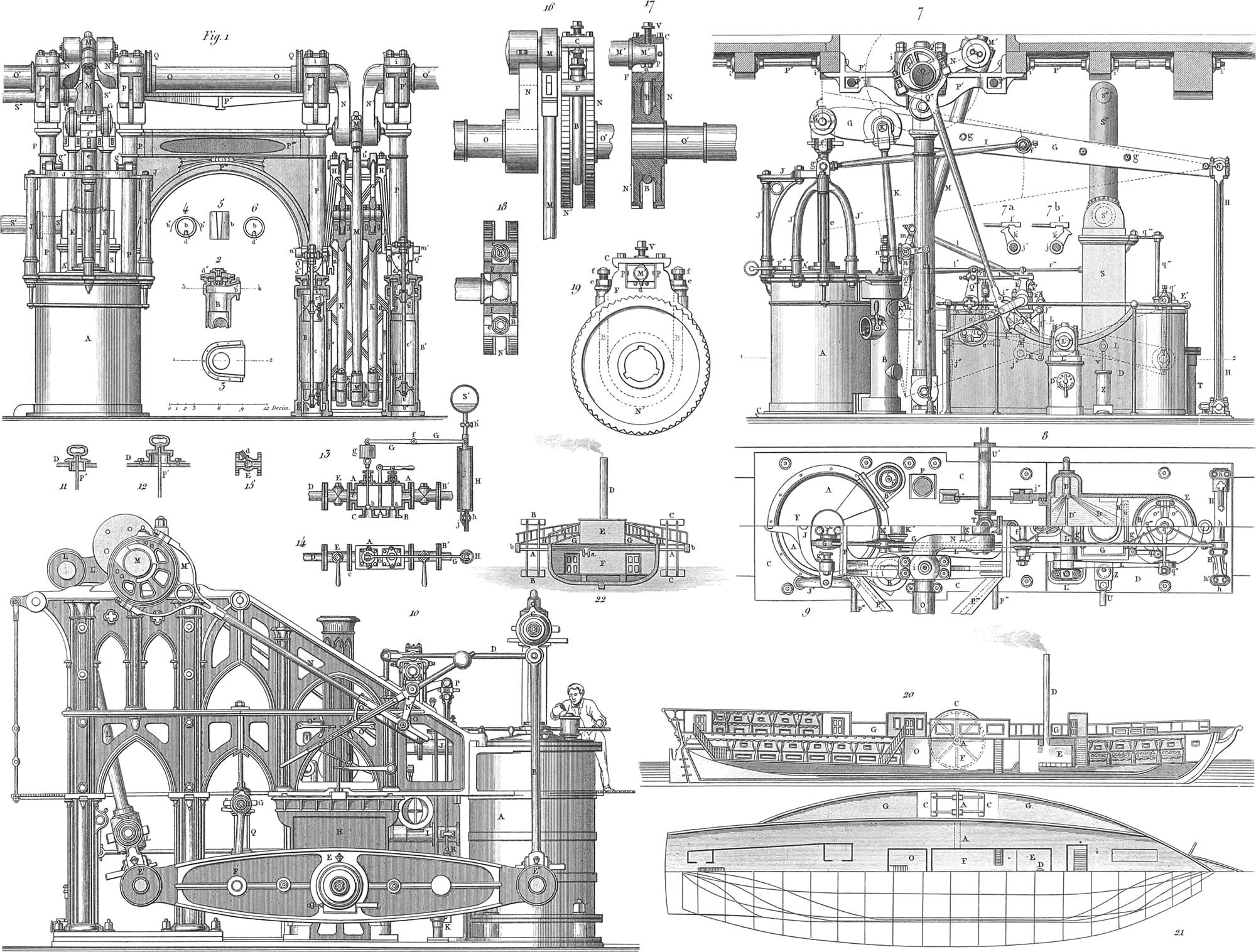
As just stated, the steam-engine is the moving power in steamships, sails being only occasionally used as an additional force, in order to save fuel. In steamships the engine is arranged either to drive paddle wheels or an Archimedean screw, the vessel being propelled by each of these moving powers. The engine generally differs little from those in common use, except that, on account of the limited space, the working-beam is either omitted or placed in a low part of the engine. As we have already described the different parts of the steam-engine (see Mechanics) we will here merely give an account of some of the best steam-engines that have been constructed for ships. Pl. 18, figs. 1 to 9, represent a steam-engine of 160 horse-power, consisting of two connected engines working on a common crank-axle, the ends of which carry two paddle-wheels, the axle passing through the whole breadth of the ship. Fig. 1 represents the two engines, the larboard engine in a front view, and the starboard one in a section through the regulating cylinder; the air-pump, the condenser, and its pipes are left out for the sake of greater clearness; fig. 2 is a horizontal section of the regulating cylinder, and fig. 3 a vertical section of the same; figs. 4, 5, and 6, are the details of a cylindrical sliding-valve; fig. 7 is a side view of the larboard engine, with a vertical section of a part of the deck; fig. 7a, and fig. 7b, are details of the regulation for the injection of steam; fig. 8 is a half horizontal section of the larboard engine, in the direction of the line 1, 2, in fig. 7; fig. 9 is a half view from above of the same engine; A is the steam cylinder, in the chamber of which, A′, the air-tight and steam-tight piston-rod moves up and down, being secured in a perpendicular direction at the top by the plate, J, which rests on the supports, J′. The piston-head, G′, raises one end of the lever, G, which moves at the other end on the pillar, H. In order that the piston-head, and the lever, G, may follow the perpendicular direction of the piston, the cross-bar, I, is applied, which turns around the gudgeon, g″, on the plate, J, and moves on the lever at f′; from the lever, G, the double connecting-rod, K, moving on the gudgeon, K′, passes to the working-beam, L, which moves on the gudgeon, K″; the working beam plays on the point L″, and at the gudgeon, K′, is a third connecting-rod, M, which runs to the crank, N, of the main axle, and causes the paddle-wheels to revolve. The lever, G, consists of two separate pieces, which are fastened together by the bolts, g; the main axle, O, rests on four bearers, P′, which oscillate on four iron pillars, P, with gudgeons at each end, of which the upper ones are connected with the bearers of the axle, while the lower ones rest on firm supports on the floor. In this way the axle is made to admit, to a certain extent, of alterations in the construction of the vessel. The two inside pillars are connected by the piece P″, and the inside bearers of the axle by the braces, P‴, while between the ship’s beams, adjacent to the engine, braces, p″, are inserted with the disks, i′. The supply of steam in the cylinder, A, is effected by means of the regulating cylinder, B and B′, into which the steam passes through the pipe, a″, with the valve, a. The connexion between the regulating cylinders and the cylinder, A, is shown in pl. 18, fig. 2, in the direction of the transverse line 1–2, in fig. 3; and in the direction of the transverse line 3–4, in fig. 2. The regulating cylinders have sliding valves, of which the details may be seen in figs. 4, 5, and 6, the valve-rod, c, being connected with the regulating apparatus of the whole engine. This apparatus is constructed as follows: On the axle, O, is placed the eccentric, Q′, from which the sliding-rod, Q″, extends to the crank-bearing, i; this bearing supports on its axis the lever, k, which is joined by the connecting-rod, l, to the angular lever, mn; this turns on the gudgeon, n′ raising and lowering the valve-rod, c, at a calculated rate of velocity; the range of this movement is determined by the situation of the arrangement i′i″i‴. An additional sliding lever, k′, is placed on the crank-axle, k, the different positions of which are shown in fig. 7a, Sind fig. 7b. This lever moves the sliding rod, l, and by means of this and the leverage, o′ l″ l‴ k‴ j″ k″ l″ j″, the steam is brought into the condenser, E, and its admission regulated; the cold water is injected by the pump, Z, the supply-pipe of which is U, and the piston-rod, V, connected with the working-beam, L; the admission of the water is regulated by the apparatus, L′; the pipe, D′, conducts the water into the condensing-trough, D; the injection is regulated by a valve, which can be regulated on the disk, D‴; the condensed water is raised to S by the hot- water pump, E, the piston-rod of which is moved by the lever, g′, of the working-beam, L, and returns through S′ and S″ to the boiler. Fig. 13 represents a self-acting exhausting apparatus in section, and fig. 14 in outline; figs. 11, 12, 15, details of the stop-cocks. A is the chamber, with the two valves, a, b, which act on the pipes, C and B; of these, a is a hand-valve and b the self-acting valve. Both valve-rods pass air-tight into stuffing-boxes on the upper part of the chest. D and B′ are water-pipes, and E the stop-cock. On the valve-rod of b is a ring, connecting it with the two-armed lever, G, which turns on f; g is a weight, which balances the ball, S′. As soon as the air is rarefied in H, the piston, h′ falls in the pipe; the weight, g, is raised at the same time with the valve, b, and the exhaustion is effected; jj is a pipe communicating with the supply-pipe, h, and the atmosphere.

Pl. 19, fig. 1, represents a longitudinal section, and pl. 18, fig. 10, a side view of the engine of 450 horse-power belonging to the steamship Albatross. In the following description the letters in brackets [ ] refer to pl. 18, fig. 10. A is the steam-cylinder, into which the steam is conducted by the regulating cylinder B, partly over and partly under the piston, and then into the condenser. C is the bed-plate of the engine, and D the condenser lying underneath. The cylinder A is surrounded by a jacket, A2, in order to prevent the cooling of the steam. A constant body of steam circulates around the cylinder, passing off as it becomes condensed into water. The upper cap of the cylinder A1 has a lubricator, s. In the steam cylinder is the piston, F, with the metallic casing, F′, and at the piston head, G′ [C], a connecting-rod [B] passes to the working-beam G [E′], and moves it up and down on its pivot, l [E]. The cross-piece I [D] is attached to the first connecting-rod, moving the lever Hh in the different positions I1 and I2, to which is hung the piston-rod, K, for the air-pump. At the other arm of G, in L [E″], is the connecting-rod, M [L], which, in the positions L′ and L″ of the working-beam G, turns the crank gudgeon N [L], and thus puts in motion the axis of the paddle-wheels O [M]. On the axis, O, is the eccentric, Q [M′], and also a second eccentric in the opposite direction. This eccentric, Q [M′], acts by a sliding rod, Q′ [N], on the regulating lever, m [N′], with a movable counterpoise, and by the regulating lever [P] on the sliding rod, J [J], of the regulating valve, B, in the cylinder, B. Pl. 19, figs. 19, 20, 21, shows the position of the different regulating levers and valves for the admission of steam over the piston; and figs. 25, 26, 27, for the escape of the steam into the condenser. The letters are the same as on the parts represented in fig. 1. On the working-beam G [E], at [F], is hung the sliding-rod for the piston-rod [Q] of the piston, R, of the hot- water pump, E, which through the valve, R′, raises the water from the condenser, D, through o′ to S, whence it returns through S′ to the boiler. The piston-rod with its head [G] passes through the stuffing-box, T. P is the frame of the engine.
The marine engine is fed from a boiler in the same manner as those used on land. Steamships are furnished with from four to six boilers. Pl. 19, figs. 12–15, represents a common boiler, one belonging to the French steamship Tancred. Fig. 12 is a front view; fig. 13, a transverse section; fig. 14, a longitudinal section; and fig. 15, a horizontal section. The same letters in each of the figures refer to the same parts. A, A′, A″, are portions of the boiler, which is heated by the grates, B. From these the flame passes through the chamber, C, and the flues, D, which run in different directions around the boiler, the smoke escaping by the chimney, F. The steam collects in the chamber, G, whence it raises the valve, efgg′, and passes through the pipe, J, as soon as it has sufficient force to raise the valve, I. The pipe H is the steam-pipe which conducts the steam to the engine. K is the man-hole for cleaning the boiler. The pipes, L, L′, L″, which are shut by the cocks, M, communicate with the atmosphere by the pipe b. The apparatus OPR is connected on one side with the cold-water pump, and on the other side with the conducting pipes of the condenser, in order to supply the boiler with water. Of late the tubular boilers, which have heretofore been used only for locomotives, have been introduced successfully into steamships. Figs. 16–18 represent a tubular boiler for an engine of 450 horse-power, belonging to the English frigate Phenix. Fig. 16 is the front view and transverse section; fig. 17, the longitudinal section; and fig. 18, the view of one half from above. A is the water chamber; B, the steam chamber; D, the furnaces with the grates, G; and the ash-pans, which are shut by the doors, e. The flame passes through F, behind the tubes, then through them, when it heats the water, which also surrounds all the heated tubes, converting it into steam, and finally passes through the front flue, I, into the chimney, C. The valves, a, give access to the tubes, for the purpose of repairing them, and the state of the fire may be ascertained by the sliders, b, b′, b″; c and d are gauges showing the height of the water. It will be perceived that here are two boilers, adjacent to each other, with a common chimney.
The earliest method of propelling steamships, and the most usual to the present day, is by paddle-wheels. Pl. 18, fig. 20, shows a longitudinal section; fig. 21, the upper part of the deck and the lower half of the frame; and fig. 22, the vertical cross-section of such a steamship. In the middle of the ship, at F, is the engine, which, by its motion on the crank a, turns the axis A, as we have seen above in the description of the steam-engine. On each end of this axis. A, are two large paddle-wheels, G, which by their revolution act as oars and propel the ship. The boilers are at E, and D is the sheet iron chimney. O is the engineer’s room, and GG are the wheelhouses. The paddle-wheels are from 11 to 35 feet in diameter, and from 3 ft 12 feet in breadth. Their frames are of wrought iron; the floats are of wood, standing obliquely to the surface of the water, in order to avoid the tremendous noise when the wheel strikes, and to diminish the loss of power which always takes place at that time. The wheels sink about the breadth of their paddles into the water. In order to take advantage of a favorable wind, steamships are fitted out with masts and a pretty complete set of sails, consisting both of yard-sails and gaff-sails. The bowsprit carries a jib and stay-sail.
The first war-steamer was built in America in 1814. It was bomb-proof, five feet thick in the sides, in order the better to resist the shot of the enemy, and consisted of two vessels connected together, one of which had the furnace and boiler and the other the steam-engine. Between the two was the paddle-wheel. It also carried masts. The main-deck bore 32 18-pounder carronades, the balls for which were heated in the furnace. It had an apparatus by which sixty casks of hot water could be thrown upon an enemy who should attempt to board. Pl. 17, fig. 6, represents a French steam-frigate with three masts, and which in case of necessity can be propelled altogether by sails. Pl. 16, fig. 6, is the Bremen steamboat Gutenberg, plying between Bremen and Bremen-haven, and carrying no sails. Fig. 7 is the American steamer Washington, built in New York in 1846–7. The deck of this ship measures 230 feet. Its tonnage is 2000 tons carpenters’ measure. The keel is 16 inches square. The frame is of white oak. The main-mast is 80 feet high and 28 inches in diameter, the fore-mast 78 feet high and 25 inches in diameter, and the mizen-mast 76 feet high and 21 inches in diameter. The bowsprit is 45 feet long, and the jib-boom 24 feet. The ship has two engines with 72-inch cylinders and 10 feet stroke. The frame, the axis, and the working-beam are of wrought-iron. The wheels are 30 feet in diameter. Each of the boilers is 36 feet long and 15 broad, and weighs 43 tons. They are tested at a pressure of thirty pounds to the square inch. The ship can make from 8 to 10 miles an hour without sails. The first cabin accommodates 142 passengers, and is fitted up with great elegance. The main saloon is 85 feet long and 22 feet broad. There are also a barber’s shop and smoking-rooms. The galley contains 575 square feet of surface and cooks for 400 persons. There is a second cabin. In the lower hold there are large iron cisterns, from which water can be carried to any part of the vessel by force pumps. The hold has 375 tons of stowage-room for merchandise. A special room is appropriated to the mail. The Washington, although long since superseded both in swiftness and elegance by other ocean steamers, deserves to be recorded as the pioneer of American Trans-Atlantic steam navigation.
It may be desirable under certain circumstances for one of the paddle-wheels to work while the other stands still; but as the axis with its crank is of one piece, such an arrangement of the wheels would be impossible. A special apparatus has consequently been invented, and is shown in pl. 18, figs. 16 to 19. Fig. 16 is a side view. Fig. 17 a cross-beam of the apparatus, fig. 19 a front view; and fig. 18 a view from above after the removal of the upper cap. The axis, O, the crank, N, and the cross-beam, M′, on each side are of one piece, and to the cross-piece is attached the connecting-rod, M, which, when moved by the engine, puts this part of the axis in motion. The place of the second crank is supplied by the apparatus. A cross-beam, M, is placed on a gudgeon resting on the screw-block, F, which is covered by the plate, C, through which the screw, V, passes, in order to secure the gudgeon, M′; f f, are two screws, which tighten or loosen the band, B; the block, F, has cogs underneath, so that when the band, B, is drawn tight it catches into the teeth of the disk, N, and makes it revolve with it. As the disk, N, and the axis, O, are concentric, this disk, as well as the axis, O, of the paddle-wheel, which is connected with it, must revolve at the same time with O. But if the band, B, is loosened by the screws, f f, the disk, N, slides and becomes out of gear with F, and consequently only the block, F, moves with the axis, O, while O′ stands still, until the screws, f f, and hence the band, B, are tightened, and the disk, N, is again brought into gear with F.
We will now consider those steamships which have Archimedean screws, or simply the screw-propellers, which have recently come into frequent use, though it is not more than nine or ten years since the first experiments with them were made.
It was desired to simplify the propelling apparatus of a ship as far as it could be done without diminishing the velocity, to avoid the risk of breaking the paddle-wheels, and to protect the motor of the vessel in men-of-war from the enemy’s fire, by which the wheel-houses were easily destroyed: the Archimedean screw fulfils all these conditions. As early as 1768 it was proposed by Paucton, a French mathematician, to propel a vessel by means of the Archimedean screw, but he was only laughed at. This did not prevent Delisle, an engineer in France, from entertaining the same plan in 1823. He suggested the application of the Archimedean screw to the marine steam-engines, but obtained no success; until at last the idea was carried into effect in England by Ericson and Smith, The earliest screws were constructed on the plan shown in pl. 19, fig. 28. They were simple Archimedean screws, only one thread winding around the axis; afterwards two threads were made use of (fig. 29), forming a double screw. The steam propeller Archimedes, in England, had a screw of the first kind. At a later period the plan was adopted of removing the inner parts of the screw which greatly increased the lee-way, and employing only segments of the screw. Meantime Ericson had applied three strong arms to the axis of the screw, in the direction of the threads; six curved segments were then bolted on the outer edge of the screw, which taken together formed nearly a whole circumference of the axis. The mean angle of inclination is 45°. The method adopted in the galliot Napoleon (which is shown as seen from above in fig. 2; fig. 3, in longitudinal section; whilst fig. 4 represents the stern parts, with the screw) is a combination of Ericson’s system and of the screw (fig. 28), the segments, of which there are three, contracting to a considerable degree on the inside, and joining the axis by a wave line, which is well adapted to cut the water to advantage, without causing too much leeway. Fig. 5 shows the construction of the wooden model for the four-bladed screw, first employed in the galliot Napoleon. Two double-armed fans, C, of wood were attached to the axle. A, and spreading out from b b1 b2, and a a1 a2 The segments or blades of the screw are thus formed, and are afterwards completed by the addition of the surfaces B, B1, B2, B3 curved from the side; these segments are seen at a1 b1 c1 d1, abcd, a2 b2 c2 d2, and a b3 c3 d3. The three-bladed screw (fig. 6) was subsequently adopted, of which a front view is shown in fig. 7. Here the blades B, B1, B2, are placed on the axis. A, with the surrounding lines, abcd, a1 b1 c1 d1 and a2 b2 c2 d2. The form which nature gives to aquatic animals was closely studied by George Rennie, who noticed that it expands towards the hinder end, like the tail of a fish for instance, while the other parts almost all run together in a point. Following this law, he gave his screw a conical form, making the surface an inclined plane which winds around a cone, so that the threads should be tangents to its surface. Pl. 19, fig. 8, is a side view of a conical screw, with the continuous blades, ee; fig. 9 is a front view; fig. 10 is a side view of such a conical screw, with separate blades, ee; and fig. 11 a front view of the same. Fig. 30 is a view from above of Smith’s propeller, which is intended as a substitute for the Archimedean screw, and fig. 31 is a side view of the same. Around the axis, n, is a disk, to which the bearers, mm, are attached, each couple of which supports a platform, like the steps in a treadmill.
In the section of the galliot Napoleon (fig. 2), A is the bowsprit, B the head, C the cabin for the crew, D the boatswain’s cabin, E the foremast, F the stairs to the cabin for the forward deck passengers, G the cabin, H the prison, I the steam chimney, J the boiler, K the main-mast, L the steam engine, M stairs to the engine, N fly-wheel and pinions for the axis of the screw, O engineer’s cabin, P officers’ and passengers’ cabin, R cabin stairs, Q mizen-mast, S the captain’s cabin, T luggage room and coal room, 1 catheads, 3 forge, 4 port-holes, S (on the stern) boat-davits, 6 rudder, 7 the screw, 8 the axis. In fig. 3, the view from above, A is the bowsprit, B the head, C the capstan, D covering of the cabin stairs for the crew, E forge, F the fore-mast, G stairs for the forward-deck passengers, H sky-light to the forward-cabin, I prison, J galley, K funnel, L the main-mast, M roof of the engine-room, N stairs to the same, O covering over the fly-wheel, P sky-light for the engineers’ cabin, Q sky-light for the officers’ cabin, R the mizen-mast, S stairs to the officers’ cabin, T sky-light to the captain’s cabin, U poop, 1 catheads, 2 port-holes, 3 chain pump, 4 coal-room, 5 feeding pump, 6 rudder, 7 boat-davits.
The dimensions of this galliot are as follows: Length of deck, 155\(\frac{1}{2}\) feet; breadth of beam, 28 feet; depth of draught, 11 feet 10 inches. The engine is of 120 horse-power; diameter of the screw, 7 feet 6\(\frac{3}{4}\) inches, length, 3 feet 6\(\frac{1}{2}\) inches. The masts carry gaff-sails for the most part. Pl. 17, fig. 2, is a French iron steam battery, with an Archimedean screw; it carries thirty-two eighteen-pounders, and is of a round build at stem and stern; it has two masts, the forward one with a main-sail, top-sail, top-gallant-sail, and also a stay-sail, while the after-mast has only a half mizen-sail and a try-sail.
![]() Manning of Ships
Manning of Ships
 Manning of Ships
We include in the manning of a ship all persons who take any part in its management. A degree of subordination is carried into effect in a fleet which is not known in the land service; but this subordination is necessary, inasmuch as not only the safety of the ship, but the lives of the whole crew and passengers often depend on the act of a single sailor, or on his negligence or disobedience of orders.
The War Marine
The manning of ships of war is usually arranged according to a fixed system. We will first consider this, referring chiefly to the organization of the French and English navies.
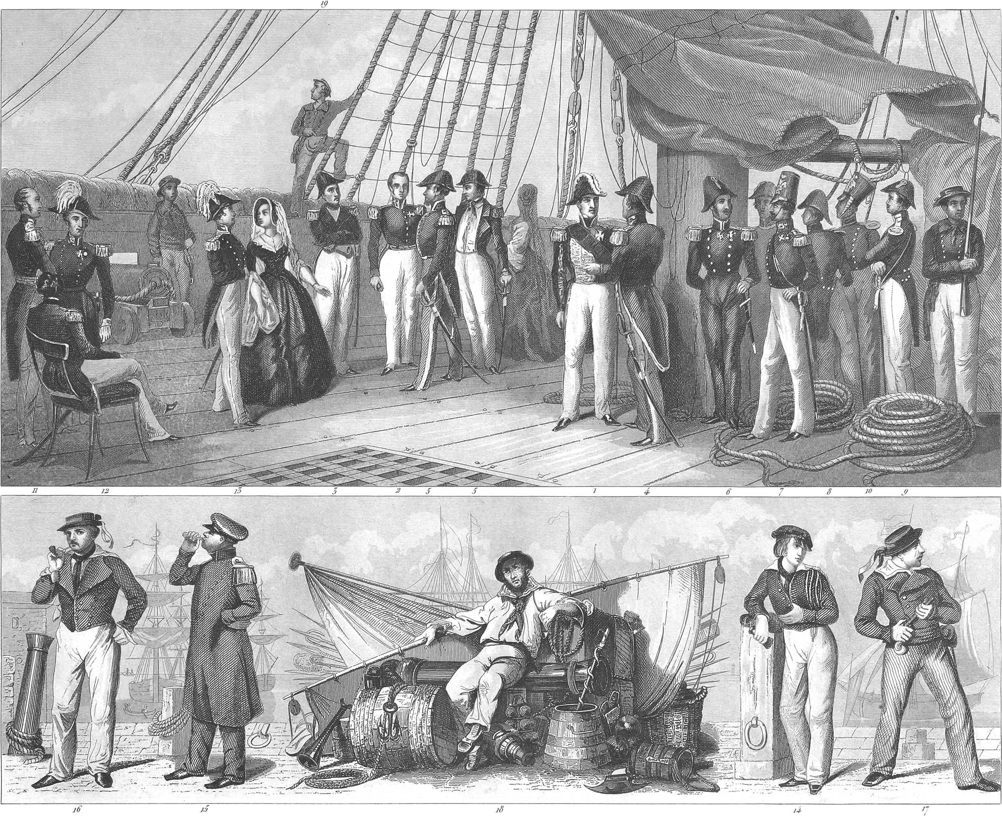
In France, the sailors are taken from among the conscripts, and are obliged to pass through a certain course. They first become sailors of the third class, and in six or eight months can be promoted to the higher classes on the nomination of an officer. A sailor of the first class (pl. 20, fig. 17, a sailor in parade-dress; fig. 18, one in working-dress) can become a quatre-maitre, with the rank of a corporal, or second maitre (fig. 16), with the rank of a sergeant, or finally premier maitre, or boatswain (fig. 15). The mechanics, caulkers, smiths, carpenters, &c., can only obtain the rank of sergeant-major. Every one who is not accustomed to the naval service is struck with the difference which prevails between the two ends of the upper-deck. Forward of the fore-mast, on the forecastle, is the general rendezvous of the sailors; while abaft the same, especially near the poop, access is permitted only to the officers (pl. 21, fig. 3), except on duty.
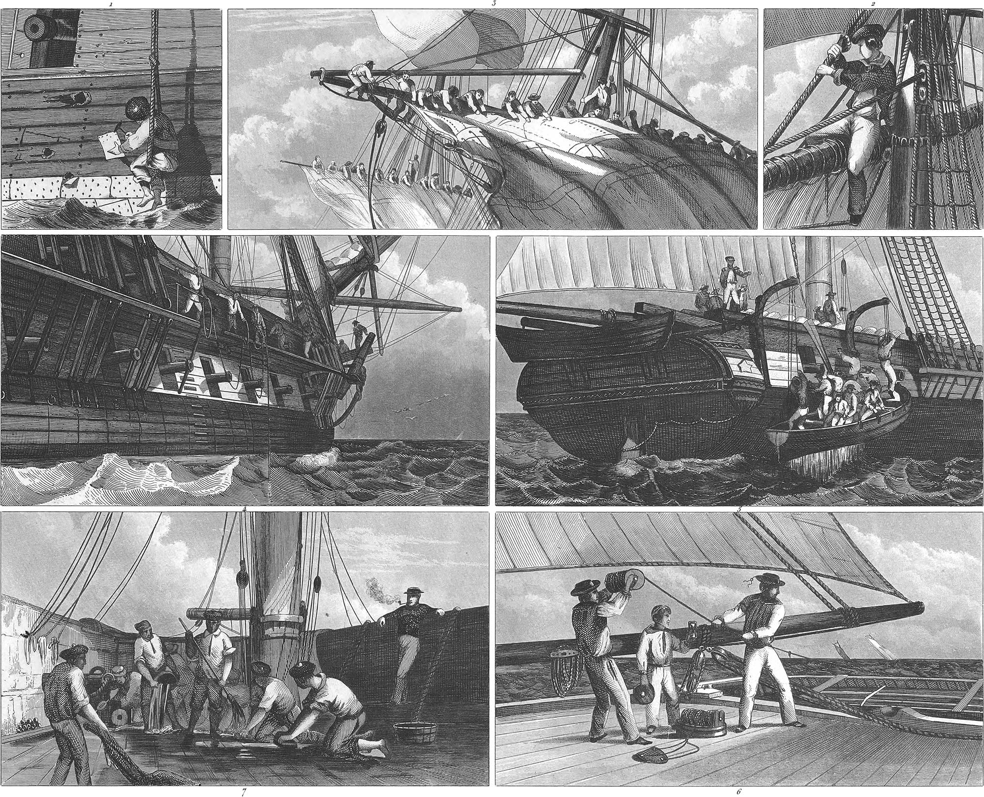
The career of a naval officer is open to every one. Pupils are received into the service, when those who distinguish themselves are sent to a naval school, which in France is on board a ship appropriated to that purpose, in the harbor of Brest. Upon entering on actual service, after passing an examination, the pupil becomes a cadet of the second class and receives a uniform. Once on board, the service commences. Ten or twelve cadets have a state room (pl. 21, fig. 6) assigned to them, which becomes the scene of their studies, their recreations, and their rest. The cadets on board are divided among the officers of the different watches. The officer of the watch is distinguished by his complete uniform and arms (pl. 21, fig. 1), which he must wear during his watch. His position is on the quarter-deck of a frigate and on the poop of a ship of the line. He has an eye upon everything which is to be done in the ship, during his time on deck. If a boat is to be got out, he gives the order by calling its name, “Long boat!” “First cutter!” &c. The boatswain’s mate, who is constantly stationed at the foot of the main-mast, gives a shrill whistle, the sailors spring to, and in less than five minutes the orders are executed (pl. 23, fig. 5). The boatswain’s mate reports to the officer of the watch, who calls the cadet on duty, gives him the necessary instructions, receives his report on his return, and issues further orders.
After a cadet has served two years in every branch of practical seamanship, he becomes a cadet of the first class (pl. 20, fig. 14), with the rank of a second lieutenant in the land service. The promotion of the cadet to the next rank is a more important one, as it classes him among the officers of the ship, with the rank of a first lieutenant in the army, and a separate room (pl. 20, fig. 5). The officers, second lieutenants, and first lieutenants (fig. 4, a French lieutenant; fig. 13, an English lieutenant), the last with the rank of a captain in the army, have a separate table. A lieutenant can command a transport ship and a steamboat. Corvettes and brigs are under the command of a corvette captain, and frigates and ships of the line under the command of a captain (fig. 3, a French captain; fig. 12, an English captain), with the rank of a colonel in the army. A division of several sail is commanded by a rear-admiral, ranking as a brigadier-general, while the vice-admiral (fig. 2, a French vice-admiral; fig. 11, an English commodore), ranking as a lieutenant-general, commands a squadron or a small fleet, which may run up even to the number of fifteen ships of the line. The highest advancement in the navy is the rank of admiral (fig. 1), who in France has the rank of a field-marshal.
In England, below the admiral is the vice-admiral, who commands the second division of the fleet, and the rear-admiral, commanding the third division. The vice-admiral carries his flag on the fore-mast, and the admiral at the main-mast. In England, moreover, the admirals are distinguished by their red, blue, or white flags, according to their station in the English navy. Pl. 20, fig. 6, is a Russian vice-admiral of the regular navy, figs. 7, 8, Russian officers of the Finnish navy, and figs. 9 and 10, Russian officers of the marine guards.
The sailors are organized into watches, something resembling the companies of the army, consisting of a lieutenant, answering to a captain of the land service; several naval ensigns as first lieutenants and cadets of the first class as second lieutenants; two mates for the sails, one for the guns and one for the ship’s course; eight quarter-masters, four of them for the sails, two for the guns, one for the carpentry, and one for the caulking; and finally, of one hundred men. Any naval officer may, in cases of necessity, be required to take the command, and incredible achievements have sometimes been performed by young men whom the casualties of the service have placed in situations of responsibility. In illustration we have represented an engagement of a weak brig of 16 18-pounder carronades, compelling another brig of superior force, having 22 32-pounders, to strike her flag (pl. 25, fig. 4).
As soon as the men are on board, the officers must assign to them their respective stations for every emergency. The order of battle comes first. This is the basis of the whole organization, and it is no easy thing to find just the right men for every post. This order is constantly practised. At any time of the day or night, the drum may beat to quarters, and every man be summoned to his station. The most active and skilful sailors are selected for duty on the tops (topmen, pl. 25, fig. 6); they are intrusted with the most difficult part of the management of the sails and ropes; they often swing on the mast-head or yard-arms, in order to arrange a rope or block, or sit during an engagement on a yard, to watch the motions of the enemy (pl. 23, fig. 2), while the ship is so tossed about by the storm that the green hand at sea has to cling to everything which he can grasp in order to keep on his legs.
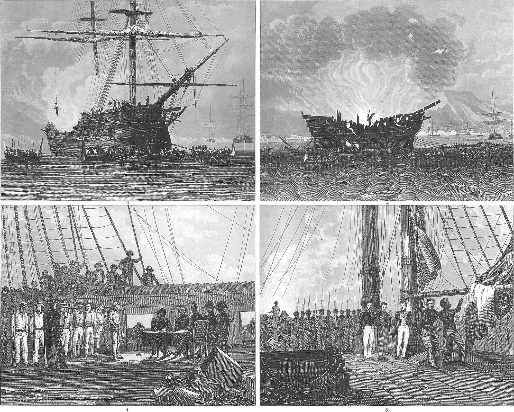
The boatswain of a ship of the line or a frigate must be a perfect seaman, presenting a model to the whole crew. He has in his charge the whole rigging of the ship, the anchors, cables, and buoys, and all damage which they receive must be repaired under his direction. The sailing-master’s mate and his men are stationed near the poop on the quarter-deck. The sailing-master, under the superintendence of his superior officer, issues orders to his mate, who transmits them through the boatswain, boatswain’s mates, and quarter-masters, to the sailors and boys. The wheel stands under the poop (pl. 21, fig. 2). As soon as the squadrons have come together, the signal flags are got in readiness, and the national flag is hoisted with all the honors at the mast-head (pl. 24, fig. 3). The hour-glass is in charge of the sailing-master, who has the command of the wheel. His mate stands at his side, to assist in case of need. Certain sailors at the wheel, under the command of a cadet or quarter-master, have the care of the flag, seeing that it constantly waves and is not struck except by orders from the commander.
The rest of the crew, who are not fit for more important services, keep the deck clean, under the direction of the boatswain’s mate (pl. 23, fig. 7), or they indulge in amusements, among which is card-playing, which is followed up without restraint in every place that can be found. This is also a favorite recreation during the watch, the deck at the foot of the long boat furnishing a card table (pl. 25, fig. 7).
There are not wanting on board ship greater or less offences, insubordination, mutinies, and the like. The laws of discipline in the fleet are accordingly very severe, corporal punishment being almost the only resource of the officers in most navies. The commander of the ship has the power of life and death, and whenever a crime or a serious violation of orders takes place, a court-martial is convened (pl. 24, fig. 1). The session of officers for this purpose is held on the quarter-deck. The accused is brought forward without fetters, and the charge is presented, while the crew crowd around the spot. After the fact is established, the court enters into secret session, and each of the judges, beginning with the youngest, gives his opinion. In most cases the punishment is flogging with a rope’s end; the English use the cat-o’-nine-tails, a rope whip with nine lashes, the ends of which are interwoven with musket balls. Keel-hauling (fig. 2), which has now been discontinued in nearly every navy, is purely a seaman’s punishment. When it is to be inflicted, a special flag is hoisted, and a gun is fired as a signal to the other ships of the fleet, which thereupon get out their boats and surround the ship in a semicircle. The delinquent is then taken under the main-yard, and his feet are loaded with a 30-pound cannon ball. The master-at-arms then reads the sentence, and the criminal is suddenly drawn up by a side tackle attached to the main yard. The rope is then slacked, and he is plunged with frightful velocity into the sea and then drawn under the keel. This operation is repeated two or three times, according to the strength of the prisoner. In the Dutch navy this punishment is equivalent to death. Smaller offences are punished by stopping the rations, especially spirits, for three or four days, or by confinement in irons (pl. 25, fig. 8). In the last punishment, the sailors are taken from arrest to their watch, and then brought back. Extra watches are also inflicted as punishments.
While a man-of-war is in port, a regular and often an unexpected visit is made by the port-guard, in order to examine whether everything is right on board the ship (pl. 22, fig. 5). The boat, in such cases, is commanded by a port-officer, and as soon as it approaches the ship it must be hailed by the guard, to whom the reply “Watch-boat” is given.
The artillery is so far subject to the direction of the commander of the ship that he has a speaking tube, the mouth-piece of which is under his control, the tube leading below the deck, through which he issues his orders. One man for every gun, during action, carries shot and cartridges from the hold (fig. 4). Non-combatants are generally selected for this duty. A very important point, which must be attended to at the commencement of a battle, is the condition of the pumps. It must be seen that they are in order and properly manned to pump out the water which enters through the shot holes. The fire-engine must also be looked after. The head caulker attends to all these points, and on the first summons to quarters takes his place at the pumps. He takes care that twisted plugs of hemp, ropes, sheet lead, nails, and plugs wound round with tow and dipped in tallow, are ready to stop up the shot-holes which are made at the water line. For this purpose slings are provided (pl. 23, fig. 1), by which men are let down to close up any such holes, and to put in a fresh caulking. If the ship draws so much water that it cannot be controlled by the pumps, it is the duty of the chief caulker to give private notice of the fact to the commander.
Manning of Merchant Vessels
In merchant vessels the discipline is by no means as strict as in men-of-war, as there is no military organization to be preserved, nor is there such a large number of men to be kept in order. The captain has the chief authority. Everything is governed by his orders, and he possesses the full power of punishment. The first mate takes his place in all cases when the captain is prevented from being at his post. It is his duty to communicate the orders of the captain and see that they are obeyed. There is also a second mate and a third mate, who strictly oversee the men, take charge of the boats on landing, superintend weighing and casting the anchor, and, in short, provide for the exact performance of all the duties of the vessel. The sailors, owing to their limited number, which in merchant vessels is always reduced to the lowest figure, perform in common the various duties which are required at sea, since they would be too weak were they divided into separate classes with special duties.
![]() Management of Ships
Management of Ships
 Management of Ships
Management of Separate Ships
1. Navigation in General. The ocean is not everywhere the same, nor is it the wind alone which changes its aspect. The different portions of the sea, the sky which is reflected in it, its natural qualities and phenomena, have their peculiar characteristics, which are not without influence on the navigation in different seas. The icebergs which float in the polar latitudes prevent us from reaching the poles. In those regions, calms and storms, fine weather and tempests, alternate with each other in a single day. During the summer, as it appears in these ungenial climates, the atmosphere is warm and pleasant in a calm; but the north wind rises, and an icy coldness takes the place of the mild air. The moving ice stretches its long furrows through the waves, and stares in strange and grotesque forms towards the sky. When these mountains of ice approach each other, they form a circle, within which the sea is quiet as in a harbor, while on the outside the waves are raging with increased violence. A ship inclosed in such a basin of ice (pl. 26, fig. 3) lies as securely as in the best harbor, but woe to it when the circle suddenly breaks up!
In the temperate climates the sea is kept in constant motion by the changing winds. The waves from the north-west in the Atlantic Ocean exercise their uniform rocking influence on ships sailing towards the Azores until they come into the latitude of the trade winds between the tropics. These are disturbed only by the equatorial currents, which separate the north-east trade winds of our hemisphere from the south-east trade winds of the southern hemisphere. Long days pass by without the surface of the ocean being ruffled by the slightest wind; the ship, with all its sails unfurled, seems to rest upon the waves (pl. 26, fig. 4); when often, as if by a freak of Neptune, a stormy wind springs up from the black clouds which rise from the sea, and the masts are broken, the sails are shivered, and the rigging is torn in pieces.
The mariner who wishes to navigate the ocean must be acquainted with all its peculiar features. For this purpose he makes use of charts, which point out the reefs which he must avoid and the course which he is to follow. When he is once at sea, the compass is his only guide. This alone can tell him the direction which he is to keep, when nothing but sky and water are before him. It is well known that the point of the magnetic needle always turns to the north, whatever be the direction of the ship, and consequently enables the mariner to ascertain its true position on the ocean. For this purpose, a thin plate of isinglass is cemented under the needle, turning with it about its centre. This circular plate, like all circles, is divided into 360 degrees. If, then, the deviation of the line of direction necessary for the voyage from the meridian line is measured by means of a circle divided in the same manner on the chart, the ship can easily be so turned, that its line of direction shall deviate the same number of degrees from the meridian, and it will thus reach its object without any other guide. In order to facilitate the observation of the compass, the circle is again divided into thirty-two parts, called points of the compass. These thirty-two points are named as follows. The four cardinal points are called north, east, south, and west. Between these are four others, north-east, south-east, &c. Between these eight points are eight others, north-north-east, east-north-east, &c., and between these sixteen are sixteen more, north by west, east by south, &c., completing the full number thirty-two. These last are again subdivided into fourths, for greater precision of steering, and designated thus: North \(\frac{1}{4}\) east, north-west by north \(\frac{1}{2}\) north, and so on. The mariner has also his hour-book, giving the true position of the stars for every hour, the artificial horizon, and the sextant, which enable him, according to the angle which the vessel makes with the stars and the horizon, to ascertain her place when he can get a good observation of the sun or of a star, as he can thus ascertain the true time of the spot where he is and calculate his position by the difference of time from his home or from Greenwich. For this purpose he has the most accurate watches and chronometers, some of the latter keeping time with so much precision that they do not lose a minute in a voyage round the world. When he can get no astronomical observation on account of cloudy weather, he calculates his position by the speed of his ship, measured hourly by the log, and by the mean direction in which he has steered. This is called dead reckoning, and is necessarily less accurate, as the influence of currents and of leeway can only be conjectured.
2. Practical Navigation. Practical Navigation, which we are now to consider, teaches the use of the sails and rudder, on every occasion, so as to produce the suitable motion, speed, and direction of the ship, in order to reach the end of her voyage. For this purpose we first have recourse to the rudder.
Whenever the tiller, and consequently the rudder, is placed in the same direction as the keel, no effect is produced; but if, while the ship is moving forward, the tiller is turned to starboard, the rudder moves to larboard, and the water striking on the ship acts on the rudder, and brings the stern to starboard, while the bow is carried to larboard, and conversely; if, on the other hand, the ship is moving backwards, and the tiller is turned to starboard, the water strikes the ship from behind, driving the rudder which stands to larboard before it, and hence sends the stern to larboard and the bow to starboard, and conversely.
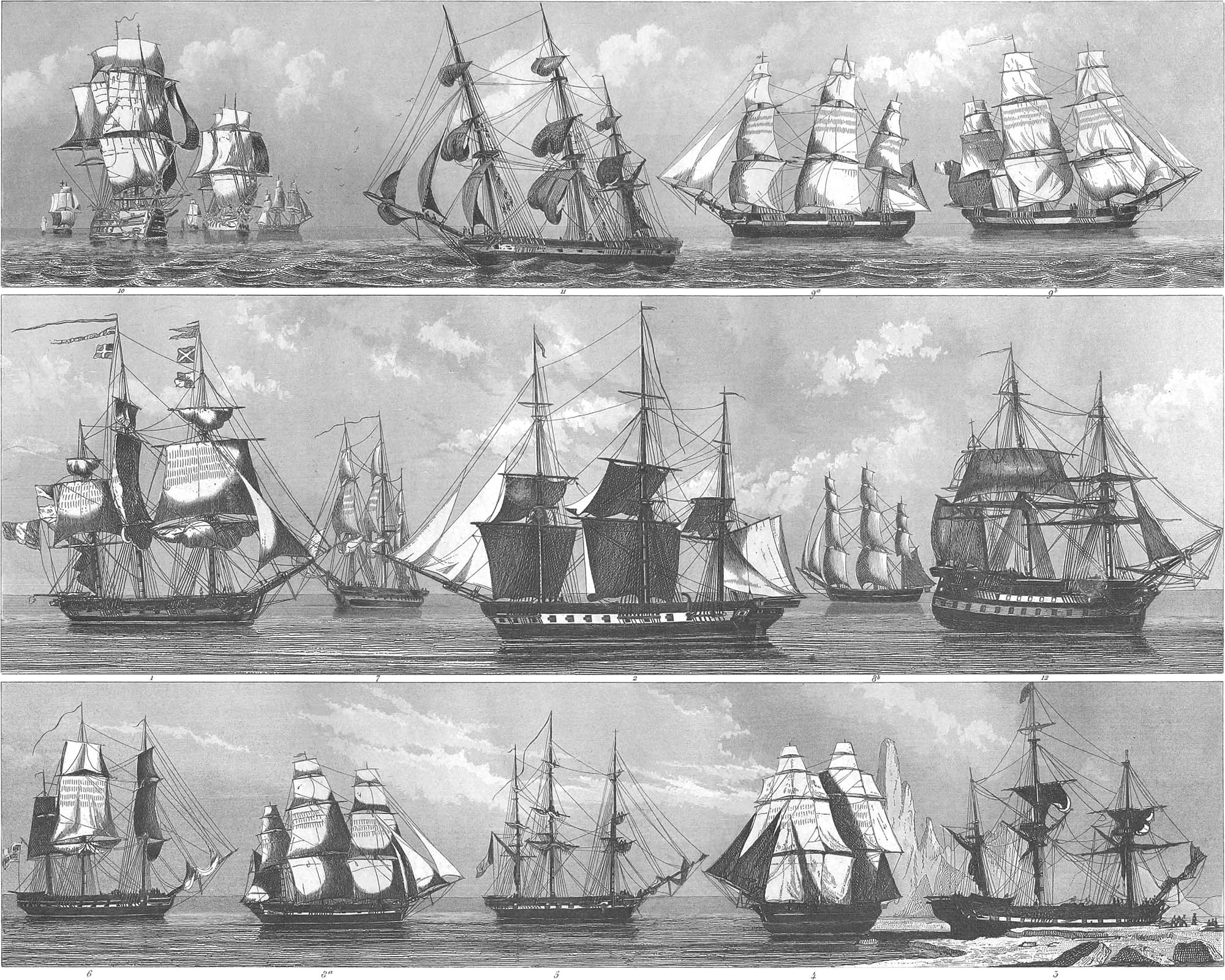
In order to explain the action of the sails, we premise the following: Suppose a weather-cock standing on its spindle during a calm, in any direction you please; for instance, the broad end to the west. Let a south wind now blow gently; it will turn the broad end before it, until it comes into the same direction with the wind. But if the rod had passed through the middle of the vane, making the parts on each side equal, the wind could produce no effect, its pressure being equal on both ends, and the vane would remain at rest. Let a ship be imagined to be such a vane, and the rod supposed to pass perpendicularly through the centre of gravity, D (pl. 7, fig. 18). Now let a three-masted ship be turned with its bow towards the west, and the wind blowing from the south, or on the larboard, we call this the windward or weather side, and the other the leeward side. If a square sail is now hoisted at the fore-mast, the lower weather clew stretched with the tack, the lee clew with the sheet, the starboard (lee) braces holding the yard in the direction of the sheet, the vessel is said to be on the larboard tack, and the sail has the double effect of turning the ship to leeward on the supposed axis, D, and at the same time of driving it forward in the direction of the keel. Let a jib now be raised on the jib-boom, with its tack fastened to the end of the boom, and the sheet drawn aft, a great power is applied to turn the ship to the leeward, as the jib is further from the line D, and consequently forms a longer arm of the lever. All the sails which are placed forward of the centre of gravity, or of the line D, will exercise this powder to a greater or less degree according to their position; that is to say, all the forward sails have a tendency to make the ship fall off, or turn before the wind to the leeward. If we now suppose a square mizen-sail stretched forward with the larboard tacks and aft with the starboard sheets, this sail will turn the ship to the starboard, and of course to the leeward, and at the same time drive her forward; but the bow is thus made to stand to windward, and the ship is said to luff, or go to windward. All the aft sails, therefore, drive the vessel towards the wind. If both mizen-mast and fore-mast sails are set, each acting with the same power, they each drive the vessel forwards; for, since the force on both sides of the axis, D, is equal, no turning either of stem or stern can take place. If the mainsail alone is raised, the tack being forward of the axis, D, and the sheet abaft of the same line, the ship is likewise driven forward without turning. If the fore-sail is braced aback with the larboard or weather braces, while the leeward tack is stretched forward, and the weather sheet aft, the action of the sail is to make the bow rapidly fall off to the leeward, while at the same time it drives the ship backwards in the direction of the keel. As the sail lies against the mast, with its forward surface exposed to the wind, it must have a contrary effect to that which takes place when it is filled, and as the wind now comes from forward, while the sail is braced aback, the sail has a greater power to drive the ship to leeward. If the mizen-sail is braced aback it drives the ship backwards, but turns the stern to leeward, so that the ship luffs. Pl. 26, fig. 10, shows vessels which luff, or bear to windward.
So much for the first principles of navigating a vessel; we will now present some cases of their practical application. Let us suppose a ship with all the sails furled (fig. 5). The object is to loosen the sails; the sailors are on deck; the commander gives his directions to the second officer, who gives the order (if, for instance, the topsail is to be unfurled), “Set top-sails!” The top-men then run up the shrouds, stretch out on the foot-ropes, leaning the body against the yard, cast off the gaskets, and sing out, “All clear!” when the order, “Loose!” is given, and in a moment the ship is covered with a cloud of canvas, behind which the sailors disappear, running down the shrouds. On deck the ends of the sail are stretched to the main or fore-yard by the topsail sheets; then the topsail-yard is hoisted to the topmast-head by the halliards; and finally, its arms set in the required direction by the topsail braces. This manœuvre is performed when the sails are to be set, or merely stretched in order to be dried. Fig. 2 shows a ship of war with a part of its sails loosened for drying.
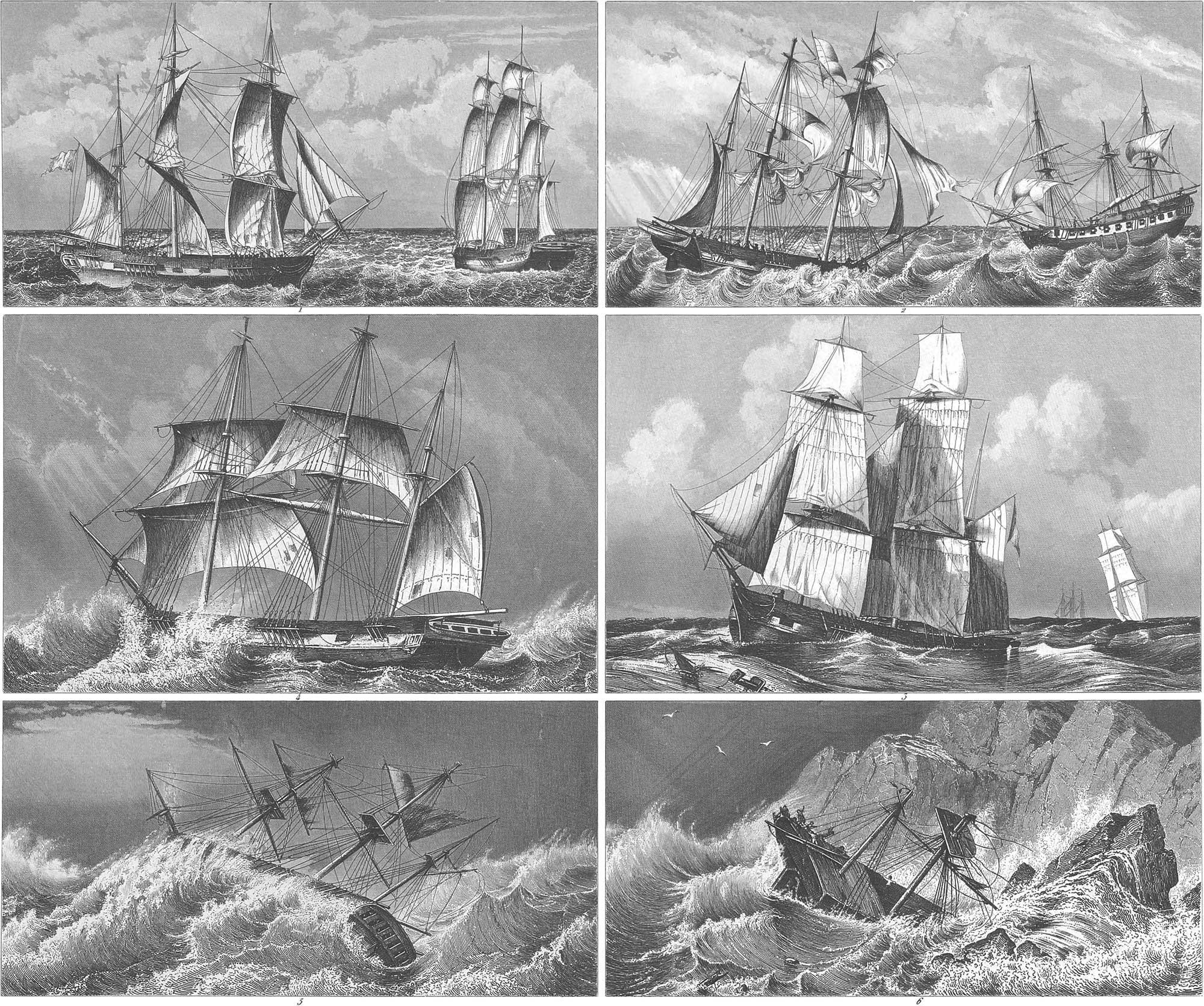
Tripping the anchor and bringing the sails to the wind is called getting under weigh. When the anchor is to be weighed a boat is sent out to the buoy, and with a small windlass raises the anchor from the ground; it is then hove up under the davits by the capstan and secured to the bow. Meantime the sails are set on the general order, “Stand by to make sail!” (pl. 26, fig. 6). The orders now follow “Loose the top-sail!” and “Loose the top-gallant-sail!” &c., on which the clew-lines are overhauled, the tacks and sheets made fast to the clews, the yards drawn up by their lifts, and the sails stretched as much as possible. At the same time the yards are braced at right angles with the ship’s axis, and so directed that the ship, as soon as it is free from the anchor, may turn round and take the wind in its sails. Fig. 7 represents a ship which has turned, with its larboard braces forward and its starboard braces aft. On the order, “Haul taut starboard fore-braces," the yards of the foremast are made parallel with the main yards, and the ship now takes the wind in her sails. Pl. 27, fig. 1, shows two ships which have got free from the anchor and have just set sail, the one to the left not having yet braced up.
It is surprising to many persons when they see two ships on the same river, or the same sea, and making use of the same wind, yet sailing in opposite directions, one to the right and the other to the left. We will here explain this operation, which is called sailing on a half wind. We will assume that a ship, with a north wind, is to sail towards the east, and in that case the wind stands precisely at right angles, or eight points, with the direction of the keel. Let the ship fall off these eight points, and head with the bow to the east, the yards being braced in the diagonal between the direction of the wind and the direction of the keel, or making an angle of four points with the keel. Under these circumstances the sails take the wind, and drive the ship forward in an oblique direction, making great lee-way; but the great length of the ship, and the water which presses against its immersed portion, offer a continued resistance, while the curvature and the slender shape of the bow permit the ship to cut the water with more ease in the direction of the keel, and thus the lee-wav is diminished and the headway increased. It is now evident that with the same wind, the yards being braced four points in the opposite direction, the ship can also sail towards the west. Pl. 26, figs. 8a, 8b, represent two ships which move in opposite directions. If the direction of the wind is not at right angles with the direction of the ship, but at some angle either greater or less, the yards in that case are not braced in the diagonal, but at an angle corresponding with the direction of the wind, and the ship sails more or less close to the wind. If the wind blows from the left hand, or the larboard side, the ship is said to sail on the larboard tack; that is, the larboard tacks draw down the clews of the sails so that they may catch the wind: the contrary is called sailing on the starboard tack. In order to change from one tack to another, or to take the wind from one to another side, the ship must be turned (pl. 26, figs. 9a, 9b). For example, if you are sailing with a north wind towards the east-north-east on the larboard tack, or west-north-west on the starboard tack, the ship can be turned either before the wind or up into the wind. The former manner of turning is less desirable, because it occasions great leeway, as the ship before the wind makes considerable headway before it can be luffed up on the other tack. The method usually adopted of going about is, therefore, that of running the ship through the wind. The helm is put hard a-lee, and consequently the ship is brought up to the wind and gradually into it, so that the sails catch it forward, when instantly all the braces and the lower sheets and tacks are loosened, and the yards swing round, taking the wind from ahead. Before the progress of the vessel, however, can be fairly checked they are braced round on the other tack, whilst the helm is brought amidships and gradually sharp down the other side of the ship, to prevent the vessel from going further through the wind than just to fill the sails on the new tack. Good sailers in this manœuvre hardly lose two ship’s lengths in leeway.
If a storm arises by which the sails are exposed to danger, it is necessary to reef them, slacking the tacks and sheets, and hauling in the clew-lines and leech-lines (fig. 11). At the same time the sailors man the yards, standing on the foot ropes (pl. 23, fig. 3), take in the sails, and fasten the reef-lines, thus diminishing the area of the sail. Pl. 27, fig. 4, represents a ship in heavy weather under close reefed topsails.
Ships sailing with a side wind have to take great care, especially when they are struck in squalls by the wind. If a ship in that case goes under full sail, the moment may come in which all the sails hang loose and flap in the wind, while the next moment the sudden force of the wind either lays the ship on her side, so that the yards and spars dip into the water, or the sails are split, and the braces, tacks, and sheets are snapped asunder. In such cases it is prudent to reef the larger sails by degrees, and to furl the smaller ones altogether. Pl. 26, fig. 12, is a ship of war under such circumstances, with only the main topsail, the mizen sail, and the jib unfurled, while all the rest have been secured. A storm, moreover, arising from these side winds combines with the violence of the waves (pl. 27, fig. 5), and often lays the ship on one side, so that it seems impossible for it to be righted. But a storm on the open sea is less dangerous than in the vicinity of the shore, when only too often cliffs and breakers, which the most practised seaman cannot avoid in a storm, make a total wreck of the vessel. Still more terrible than a storm is a fire on board ship, as it is only in rare cases and when it is early discovered that it can be extinguished, and everything is irretrievably lost unless the boats can be got out in season. A ship on fire usually burns down to the water-line (pl. 24, fig. 4, shows the burning of the ship of the line Trocadero), when the keel falls off, or the ship bursts open with the heat and sinks, or finally the powder magazine takes fire and blows everything to pieces.
Manœuvres of Fleets
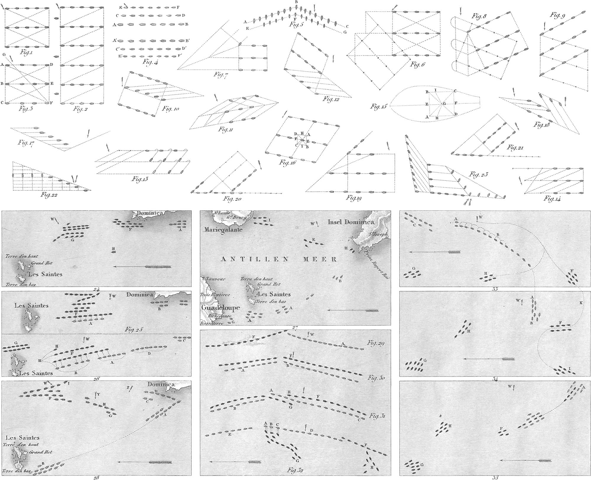
The purpose of naval tactics, or the manœuvres of fleets, is to keep the fleet always in the position in which it can first secure its own safety, and then, under all circumstances, to annoy and, if possible, to conquer the enemy. The best sailing order is represented in pl. 28, fig. 1. The fleet is divided into three columns, sailing parallel with the line which it is to take in battle. The windward column, under the command of the vice-admiral, usually forms the van-guard; the leeward column, under the command of the rear-admiral, forms the rear-guard; although circumstances often render a change in this order necessary. If the fleet is very large (fig. 2), each column is broken into two, making six in the whole. The admiral’s ship then moves before the centre of the two columns belonging to each. The determination of the distance between the columns is always a matter of importance. The length of the column being known, if (fig. 3) the perpendicular CH, equal to CF, is raised on the column CF, the points F and G connected, and FH taken equal to FC, then GH will be the right distance of the columns. (By mistake of the engraver the letter H is omitted in the figure; it belongs at the intersection of FG and AE.) This is evident when we look at the first ship, C, and the last ship, E, standing equally close to the wind, to which the line CE is perpendicular. An approximate proportion for the distance is five twelfths of the length of the column.
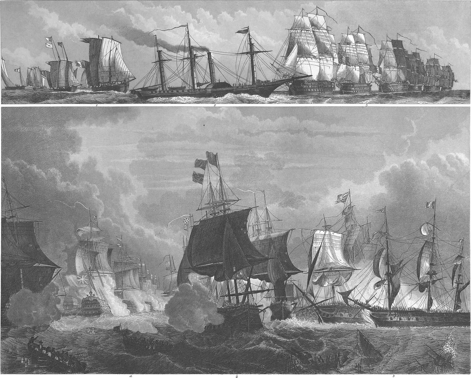
The distance between two ships varies from forty to one hundred fathoms. In pl. 28, fig. 4, AB and A′B′ are two rows of hostile ships of the line drawn up in order of battle; CD and C′D′ are frigates and fire-ships, the last stationed on the wings or centre and protected by frigates on the bow and stern. The last lines are so arranged that they lie to the windward if the enemy is to leeward, and conversely. In the rear of these are two more lines, EF and E′F′, formed by the hospital ships, transport ships, &c. Pl. 29, fig. 3, shows a division of a fleet in the line of battle. Fig. 2 is a steamship, employed to carry messages from one line to another. Frigates were formerly used for this purpose. Steamships, however, on account of their swiftness and ability to move in any direction, are far more convenient. Fig. 4 represents the moment of battle. At a are seen the two battle lines, and at b the grappling between two hostile frigates.
The order of retreat is shown in pl. 28, fig. 5, although in fact this is usually governed by circumstances. The fleet is here formed in two lines, AB and BC, forming an obtuse angle, the vertex of which is made by the admiral’s ship in the centre of the fleet. The frigates, fireships, &;c., form two other lines, EF and FG, to the leeward of the former.
It is important to know the different methods by which manœuvres can be performed in one and the same sailing order, without breaking it. We cannot here consider the subject at length, but must be content with representing the movements by figures, with a few words in explanation. Figs. 6 and 7 show two methods, by which columns can sail both by day and night without disturbing their ranks. Fig. 8, the columns turn before the wind. Fig. 9, the columns sail in two different directions close to the wind. Fig. 10, manœuvre by which the centre column is changed into the windward column. Fig. 11, change of the windward column into the leeward column. Fig. 12, change of the centre column into the leeward column. Fig. 13, manœuvre of the windward column in order to sail to the leeward. Fig. 14, manœuvre of the leeward column in order to advance to the leeward.
When the admiral has ordered a ship to a certain position, it is the duty of the commander of the ship to obey the orders promptly, and to make good the position required, cost what it may. For this purpose, the so called ship’s square has been invented (fig. 15). Let the figure be the ground-plan of a ship, EF a portion of the longitudinal axis lying over the keel, and ABCD a square in which the line EF passes through the intersection of the two diagonals, then will the angles DGE and CGE be each equal to 135°, and these will be the two courses in which the ship sails close to the wind. If now these angles are bisected by the lines GH and GI, these lines will indicate the direction of the wind on the tacks. Hence, if a ship in the direction EF sails on the starboard tack, its course by the wind will be on the semi-diagonal GD, and if it sails on the larboard tack in the direction EF, its course will be on the semi-diagonal CG. Applying this result to a fleet, which sails in three columns, the front coinciding with the direction of the wind (fig. 16), it follows that all the ships must sail parallel with each other and the line drawn through the main-masts of three ships (one of each column) will, in like manner, be parallel with the front line. If we now place the ship’s square around the centre ship, the coinciding ships in the columns, as respects the tacks and the winds, will lie in the direction GH and GI, while the ships of each column with their longitudinal axes lie in FE or parallel with it.
The ships sometimes by accident fall out of the line, and it is important to restore the line of battle immediately. The chief rule in this case is for the ship which was at the head of the line to pass to leeward behind the front, and taking the wind in the proper sails, to return into the line. The other ships following this, set their sails, according to the distance, in order to come into the direction of the first ship. Fig. 17 shows the position, when it is desired to change the line of battle without forming the ships into columns. This is effected by turning all the ships at the same time, while the last takes the wind on the other tack, and remains in its place, the other ships falling off two points, and sailing on until they come into the direction of the stationary ship. The last ship by this evolution takes the place of the first, and the left wing of the right. But if the first order is to be preserved, the first ship veers round in its place and strikes out the course of the new line, on which it sails forward, while the other ships, one after another, veer round in the same place and follow the direction of the first.
A very beautiful manœuvre is the change from one order of sailing to another. We will here illustrate two cases. Suppose that it is required to change the sailing order into the line of battle in the same direction, while the lee column remains as it was (pl. 28, fig. 18). In this case the lee column keeps as close as possible to the wind, the centre column falls off two points, and passes to the head of the new centre column, while the windward column veers at once in its position, and with seven points of wind sails to its new station on the wing. A second case, when the line is formed from the sailing order in another direction, is represented in fig. 19. Here the windward column commences the manœuvre, turning about in column into the new line, while the centre and lee columns remain stationary, until they also sail into the new line, and then tacking, complete the new line of battle.
The manœuvre of forming columns from the order of battle is shown in fig. 20. The right wing here forms the lee column, and the first ship tacks, the others of the same column following. The first ship of the centre which is now to form the windward column, proceeds with its column in the line of battle until it arrives at the point where it can tack into the new direction; it then leads its column into the right line, and at the proper distance, while the left wing, which is to form the centre column, follows the windward column to the point where the first ship tacks and leads its column into the open space. Fig. 21 shows the same manœuvre, where the columns are to be formed on another point.
In our examples hitherto, we have supposed that during the manœuvres the wind remains unchanged. If the wind shifts ahead, it is difficult to restore the order of battle, especially if the enemy’s fleet is in sight. If the wind comes from one up to six points ahead, and it is desired to restore the order on the same point, each ship, after it has fallen off, adds a few points, with the exception of the foremost, which diminishes the same number. The number of these points is ascertained by deducting from eight points half the points by which the wind has shifted; for example, if the wind shifts 5 points forward, 5\(\frac{1}{2}\) points must be added to the course. As soon as the first ship falls off and begins to sail in the new line, the second and the rest follow, until the whole lie close to the wind in the new line.
Fig. 22 shows this manœuvre. The last example which we will here give is that of changing a battle line into a retreat line with the wind ahead (pl. 28, fig. 23). After the fleet has fallen off, the first ship goes four points free, while the others keep close to the wind, each following exactly in the wake of its leader. When the first ship of the centre column arrives at its turning point, that is, in the wake of the second ship before it, it tacks and the ships of its column follow. The lee column is formed in the same manner.
As an example of the manœuvres of a naval battle, we will describe in figs. 24–33 the principal points of the engagement between the English and French near the islands of Martinique and Guadaloupe, which was fought April 8–12, 1782.
On the 8th of April, the cruisers before Port-Royal Bay at Martinique brought intelligence that the French fleet with several transport ships was under weigh. The British fleet, which lay to the northward of Cross-Islet-Bay, near the west point of Martinique, instantly set sail and pursued the enemy with an east-north-east wind, guided by his night signals through the whole night, until morning, when the Valiant discovered the enemy. Fig. 24 shows the English fleet at 2 o’clock in the morning of April 9th, when it fell in with the French fleet, F, at Martinique. At half-past 5 the signal for battle was given, and the line of battle formed. G shows the position of the French fleet at 5 o’clock, on the starboard tack, in order to go with the wind into the channel between Martinique and Guadaloupe. A single ship, H, stands so far to leeward that it must have been taken, if the wind had not been unfavorable to the English. Fig. 25 shows the van-guard. A, of the British fleet, which was engaged in close action with the centre of the French fleet from 9 to 10 o’clock. The centre and the rear-guard of the English fleet lay at B, under Dominica. F is the position of the French, some of whose ships did not come into the line, because they did not catch the wind. It may be seen from fig. 26 how A, the centre of the British fleet, gained the wind and joined the van-guard, B, about noon. The rear-guard, which lay under the wind at C, formed in the line, D, and a second cannonade ensued of about one and three-quarter hours. F is the position of the French, who kept at a great distance, thinking that the shot of the English would not reach them. Afterwards they put the head of the fleet in the position HH. G is the fleet of transport ships. Fig. 27 shows at A the British fleet on the morning of April 11, with two ships, G, of the French, which had been chased into Bas-Terre in Guadaloupe and destroyed. Two others were soon found at H, near Dominica. A general chase was then ordered, as four French vessels, at I, were still seen from the mast-head of the Formidable, Lord Rodney’s ship. The French admiral. Count de Grasse, gave chase to the Agamemnon and some other ships at B, in order to secure his ships at H, but without success. We come now to the events of April 12. At 6 o’clock in the morning, the English fleet (pl. 28, fig. 28) had changed its position from B to A, taking advantage of the wind which blew from W. The French fleet was discovered in some confusion at F. One of the ships lay quite to leeward at G. It had lost its bowsprit, the fore-mast was lying across the deck, and the ship was in tow by a frigate. The wind had veered round to Z. The Monarch and the Valiant made an attack on these ships, while Count de Grasse hastened to their aid at H. At 4 or 5 o’clock the van-guard of the English was at D, and as it was supposed that Count de Grasse had come too far to leeward to avoid an engagement, the Monarch and the Valiant were recalled into the line. The French, who perceived their position, took the larboard tack, hoping that as the wind had veered to Y, they might regain their former point beyond the reach of the English guns, especially as the rest of the fleet were gathering round them. The lines A and F (fig. 29) show the position of both fleets at half-past seven in the morning, when the Marlborough, the first ship of the English, had reached the fifth ship of the French fleet. The signal for closing the line and joining battle was now given. The effect of this manœuvre was to throw the ships on both sides in the position represented in fig. 30, where each French ship stood opposite to an English one, with a vigorous interchange of shots. The French fleet at F had gained the weather-gage of the enemy; the British admiral’s ship, the Formidable, was within half musket-shot of the fourth French ship; a hot fire was kept up along the whole line, until a space appeared in the French line making a breach possible, separating the van-guard from the rear, and compelling the first ship of the French rear to go to leeward towards G. Fig. 31: A is the Formidable, the British admiral’s ship; F, the Ville de Paris, which bore the flag of Count de Grasse; B, the English vanguard, lying opposite the cut-off part of the French line; H, the last ship of the French van. In fig. 32, we see the Formidable, the Namur, and the Drake making a hot fire at A, B, and C, on the first three ships of the French rear-guard, which effected a retreat to G. F is the French vanguard, which in two divisions attacked the English line, while the centre column sailed to the westward towards H. As soon as the French van had passed the English line, it separated into two divisions, one of which, the centre division, consisting of six ships, sailed westward towards H (pl. 28, fig. 33), while the other, with twelve or thirteen ships, sailed to the south-south-west, towards F, with Count de Grasse. A is Lord Rodney’s ship with a part of the centre in pursuit of the enemy’s vanguard, and B is the British rear-guard performing the same manœuvre. Count de Grasse now attempted to unite with his southern division, F (fig. 34), and form a new line of battle. This, of course, modified the plan of the English fleet, which pressed down towards AB, upon which the French tacked away in the direction of I. The centre division of the French, H, now attempted to follow the division G. Fig. 35 finally shows the south division about 6 o’clock. The English had overtaken it; and it turned to the northwards, when it was inclosed by the British fleet, A. Count de Grasse then struck his flag, and five French ships, F, were taken. The ships H reached those lying at G, and with them effected their retreat.
Signals
For communication between ships at sea from a distance beyond the range of the speaking trumpet, or for private interchange of notices, advice, questions, or orders even within that range, a system of signals has been devised which is equally simple and perfect. It consists of ten different small flags of easily distinguishable colors and designs. Each of these flags has the value of a figure, the ten representing 1–9 and 0. With these flags any number can be expressed, they being drawn up at the mast head one above the other, the lowest representing units, the next tens, the third hundreds, and the uppermost thousands. The necessity of quickly changing signals prevents the use at the mast head of more than four number-flags at a time, as a greater number would easily get entangled in the rigging, and would also occupy so much room as to hide the lower flag behind the upper sails. The number of signals is therefore limited to 9999. In order to do away with the restraint of this limit, however, the system has been enlarged by introducing small pennants of various descriptions above the number-flags, giving to the numbers shown under each of the pennants a different signification. As an example we will suppose a white pennant over the number-flags to have been adopted for general orders and a red one for inquiries of all kinds. The number 1357 under a white pennant would then perhaps convey the order “Prepare for action,” whilst the same number under a red pennant is perhaps the question, “Is there any ice in these parts?” It is evident that this method admits of an unlimited number of communications. The value of the numbers is preconcerted and recorded in signal-books which are kept on board of every ship belonging to the same fleet or nation. Besides those signal-books that are published and therefore accessible to everybody there are also private signals given under special pennants, or in a special place of the rigging, the import of which is only known to the first and second in command, and which are recorded in the private signal-books, of which there are two kinds; the one adopted for all cases of secret communication between the higher officers of a fleet; the other prepared for a specific occasion and only referring to the emergencies of that one expedition. In time of action all orders of moment emanate from the admiral’s vessel, which mostly occupies the centre of the line of battle. In order that the signals given by the admiral may be at once known to the whole fleet, repeating frigates are stationed in the rear of the line, whose duty it is to repeat the signals of the admiral as fast as they appear, the positions of these frigates being so taken that all the vessels of the line can see one or the other.
In the merchant service the same system is adopted for the exchange of names, destination, position, &c., and a very extensive series of questions and answers relating to marine affairs has been prepared and published in a signal-book by Captain Marryat, which is now found on board of nearly every merchant vessel.
For communications at night a similar system of signals has been adopted consisting of lanterns of various colors and displayed in various combinations and positions in the ship, either on deck, in the shrouds, in the tops, or at the peak. The signal of a wish to communicate at night is given by rockets or Bengal lights. A ship signalizing with flags is represented in pl. 26, fig. 1; night signals in pl. 25, fig. 5, a, b, c.
![]() Harbors, Naval Arsenals, and Light-Houses
Harbors, Naval Arsenals, and Light-Houses
 Harbors, Naval Arsenals, and Light-Houses
Harbors
In order to furnish a safe berth for vessels when they are not at sea, for the purpose of taking in or discharging their freight, a place is necessary where they can find a good anchorage and a secure protection from storms. Such places on the sea-coast are called harbors. A good harbor must have a situation suitable for its objects, whether intended for men-of-war or for merchant vessels. This is the first requisite. It must, in the next place, be entirely protected from storms by the adjacent coast. Lastly, it must possess a sound, tenacious bottom of clay or mud. A sand bottom also may be used, but a rocky one is wholly impracticable. If a harbor gets stopped up with sand, it must be dredged, for which purpose two different kinds of machines are used. One is the common dredging machine (pl. 31, fig. 6) which is most serviceable on flat and gravelly bottoms. It consists of a flat-bottomed boat, which is towed by a vessel to the place where it is to be used. The tow-ropes run on a windlass, so that the position of the boat can be changed without tacking the ship. The main part of the machine is a large wheel, with a rope winding on its axis, by which the dredging-box is raised. This is fastened to a long handle, which also rests on the axis of the wheel. As the rope unwinds, the dredging-box sinks to the ground, taking a part of the bottom as it is drawn away. It is then brought to the surface of the water by the further revolution of the wheel, its contents are discharged into a boat, and the same process is repeated. A far more effective machine is the steam-dredger, of which pl. 30, fig. 8, exhibits a view seen from above, and fig. 9 a longitudinal section. The foundation of this also is a flat-bottomed boat, in which is the steam-boiler A, with the safety-valve C, and the chimney D. The steam passes from the boiler to the engine B, which by means of a fly-wheel b, and different cog-wheels, turns the axis m. At the end of the axis, a mitre-wheel moves the wheel F, on the pentagonal axis of which the bucket-chain FF revolves, bringing the sand to the surface, where it is discharged into the mud-scow G. By means of the chain t, which passes over the beam o, of the windlass g, the bucket-chain can be raised or lowered by the pulley p. Artificial harbors like those of Dunkirk and Toulon (pl. 32, fig. 2) require extensive and costly works, as the whole system of dams which inclose the harbor must be erected from the bottom of the sea. As scarcely any use can be made of sails in harbor, vessels are towed to the spot where they are to cast anchor (pl. 30, fig. 2. In the vicinity of a harbor is usually found.
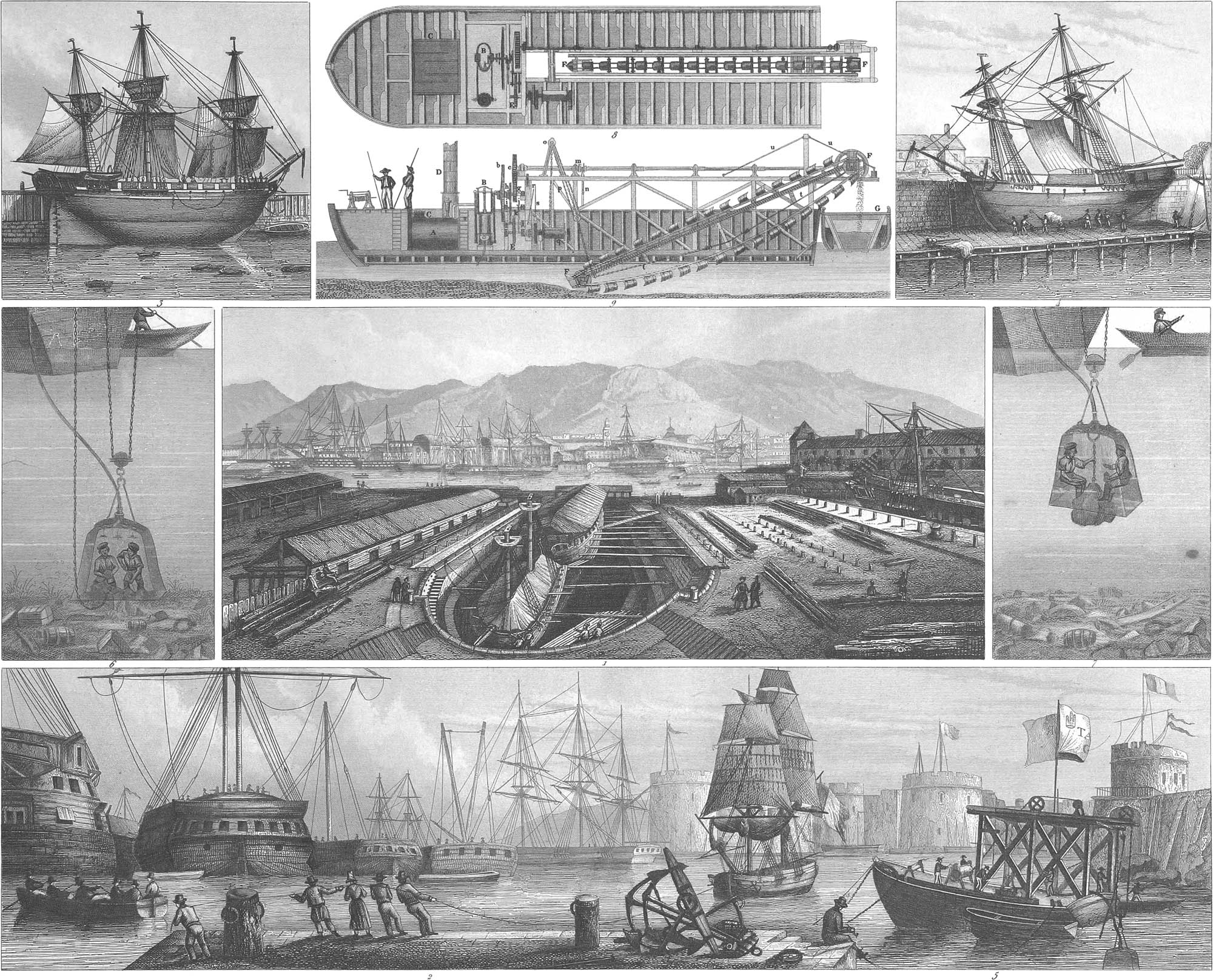
The Roadstead
This is a place of anchorage where vessels may lie at anchor more or less protected from storms, for the purpose of discharging or of taking in a portion of their freight. A roadstead is either inclosed or open (pl. 31, fig. 1, where a division of a fleet is lying at anchor); in the latter case it is only a good landing, but affords no protection to ships, except a convenient anchorage. An inclosed roadstead (fig. 2) is so surrounded by the land and the adjacent heights, that it protects vessels from the ocean winds.

Docks
A deep basin is usually made on one side of a harbor, or in large rivers, which is filled with water by means of sluice gates, and is then again laid dry by means of special sluices on the sides. Ships are sometimes taken into these docks, for loading and unloading; but they are most generally brought in to be repaired. The docks are so arranged, that they are of equal height with the low-water mark, so that the ship can be taken in and out at flood-tide. This kind of docks is called wet docks. Dry-docks are those mentioned above, which can be laid dry by means of special sluice gates. Pl. 32, fig. 9, shows a section of the Dundee Dry-dock. Fig. 10 is a view of one half seen from above. Fig. 11 is one half the transverse section at the end, and fig. 12 one half of the transverse section near the sluice gate, a is the dock, b the stairs leading to the bottom, c the sluice-chocks, d the gate, e the floor, the forward floor, g and h locks for letting the water off and on, i and k openings to the sluice gates.
Fig. 11 shows the blocks on which the staging for the ships is placed. Pl. 30, fig. 1, shows the dry dock in Toulon harbor. In it are two ships building. Another construction is shown in the Prince’s Docks at Liverpool, of which pl. 32, fig. 3, shows a transverse section of the chamber, fig. 4 a transverse section near the mouth of the sluice. fig. 5, the profile of the western wall, and fig. 6 the profile of the same wall near the sluice-mouth. Fig. 7 is the profile of the wall of the London dock. It is lined with iron. Fig. 1 is the ground plan of the West-India docks in London They are wet docks, intended only for loading and unloading vessels. On their account store-rooms are built in their vicinity. The South docks and Timber docks are used for repairs. Harbors and docks, where they adjoin the water, are provided with quays, up to which the ships can be brought. These quays are of considerable height, with deep sides, and are usually built of stone. Fig. 8 shows the profile of the Mersey quay in Liverpool.
Ship Yards and Machines
A good harbor is usually provided with ship yards, places where new ships can be built on the stocks, and old ones brought in for repairs. In a ship yard, there are ways, which are dry at ebb-tide (pl. 30, fig. 3), on which the ship is placed by the tide or by machines, when it can be laid on its side, and new coppered or caulked and graved (fig. 4). There are also stocks (pl. 31, fig. 5), on which new ships are built. These are afterwards covered over with an arched roof, which protects them from the weather. Fig. 3 shows a crane for setting masts. This machine is sometimes movable, and in that case placed on a scow. Fig. 4 shows a pile-driving machine, for the purpose of driving posts and pile-bottoms into different places in the harbor.
Arsenals
Navy yards, or harbors for men of war, always have an arsenal, where the equipments of ships are kept and also manufactured. Here are found cannons, balls, bombs, anchors, and so forth. There are also a forge for anchors, a cannon foundry, an iron foundry, a rope walk, a sail-maker’s loft, and in short, all the mechanics’ shops in which the utensils of a ship are made.
Diving Bells
A very useful apparatus, the diving bell, is also kept in harbors and roadsteads. It is well known that when a bell is immersed in the water, the presence of the air inside counteracts the power of the water, so that if the bell is of sufficient size, one or more men can descend in it to the bottom of the sea, and there pursue their labors (pl. 30, fig. 6). For this purpose, a frame with a strong tackle is fitted on a boat, by which the bell is suspended. This is then let down with men in it, who remain at the bottom until they give a signal to be drawn up. They take ropes and chains with them, which are attached to any object which they wish to save and this is drawn up together with the bell (fig. 7). In order to supply the men with fresh air, leather hose pass to the surface of the water, provided with valves. By means of them the bad air is discharged, and fresh air supplied.
Observatories
Observatories, with signal-lights for night use, are erected for the purpose of seeing ships as they come into the harbor, and of noticing everything which may occur on the water and of reporting arrivals by signals (pl. 4, fig. 8). Pl. 31, fig. 2, and pl. 30, in the lower corner at the right, show several of these observatories.
Light-Houses
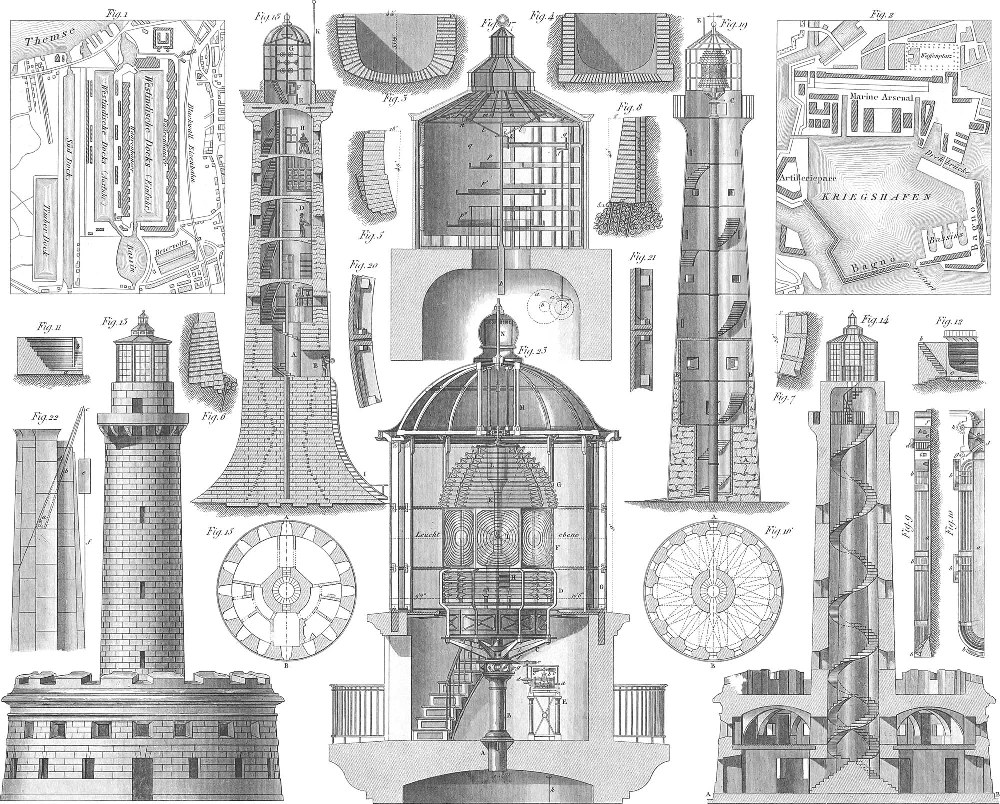
Many dangerous points are found on coasts, where sailors who are not acquainted with the locality, or who have no pilot on board to take them over the dangerous places, are very liable to suffer shipwreck. These points are designated by signals. High towers are erected, in which lights are kept burning all night. Light-houses are also built at the entrance of harbors (pl. 4, fig. 6). In the earlier ages, fires were made use of as signals; but at the present day, lamps, provided with reflecting apparatus on a large scale, are employed. As this light might be easily mistaken for a star, they are so arranged that the light is shown only at intervals, or periodically changes its color. There are:
- Light-houses with stationary, intermitting lights. The Trieste light-house is one of these. Pl. 32, fig. 13, is a front view of this light-house; fig. 14, a vertical section. The lower part of the tower is a casemated fortification, for the protection of the harbor. Fig. 15 shows the ground plan of the basement, in the direction of the line AB; fig. 16, that of the casemates in the direction of the line AB in fig. 14. The lighting apparatus is represented in fig. 17: p, p1, p2 are frames for the stationary lamps, in a lantern provided with glass windows. On the stationary post k is a frame, lmno, resembling an umbrella, to which is attached a perpendicular screen q, covering one half of the inside of the tower. This frame is made to revolve by the wheels abcd and fghi, which are moved by clock-work, so that the screen, q, at one time leaves the lamps free and then again conceals them.
- Light-houses with revolving, intermitting lights. The Bell Rock light-house, which was erected in 1811 on one of the most dangerous rocks near Dundee, is of this kind. Fig. 18 is a vertical section. The tower is washed by the waves, and the entrance, consequently, is above the range of the breakers at B; A, C, D, and E are the different stories of the light-house, in which the keepers live. At H is the watch-room; G is the lantern; K is a flag-staff, on which a signal flag is raised in the day-time. The lighting apparatus consists of an upright axle, which is turned by means of the clock-work F, and turns with it a frame, of which one half is a semi-cylindrical screen, plated on the inside, and highly polished, while the other half bears seven large and brilliant Argand lamps. As the axis revolves, the dark side of the screen and the burning lamps are presented alternately.
- Light-houses with revolving, intermitting, colored lights. Of this kind is the Cordouan light-house at the mouth of the Garonne (fig. 23). The polyzonal lenses, I, invented by Fresnel are here used, by which nearly all the rays of light are thrown in parallel lines, while those which fall above and below are also thrown into parallel lines by the parabolic reflectors H and K. The apparatus consists of eight lenses, in the focus of which is a large Argand lamp, four inches in diameter, with its chimney, L. Four of these lenses are shaded green. The whole apparatus, with its foot, D, stands on the plate of the column, B, supported by the wheels, g. Above g is the cog-wheel f, in which plays the pinion, e, of the clock-work, E, which is moved by the axis d; bc is a regulator with arms and conical pendulum.
The necessity of erecting light-houses in distant places, where skilful workmen and the requisite building materials are not to be had, has suggested to the English the idea of iron light-houses, which can be taken in separate pieces to their places of destination and there put together. Pl. 32, fig. 19, represents a section of an iron light-house constructed in London a few years since for the Bermuda Islands. The foundation up to the first story is built of stone, although the iron work commences in this portion of the building. In the second story the wall is much lighter, and is plated with iron plates on both sides. From the third story upwards iron plates only are used, which are shown in their upright joints (fig. 21) and in their horizontal ones (fig. 20). They are fastened with cast-iron flanges on the inside by strong iron screws. The stairs, floors, window frames, and lanterns are all of cast-iron. C is the clock-work; D, the lighting apparatus; and E, a lightning-rod. The tower was erected without any scaffolding. On the floor of each story (fig. 22) a projecting derrick, d, was arranged, with a windlass at its foot, a. The rope of this, b, passed around a pulley, c, and raised the plate e, which was steadied below by a guy, f. A considerable number of these light-houses have been erected with success.
- The figures in brackets [] refer to pl. 10, figs. 1, 2. ↩